Fall detecting device and fall detecting method

a technology of detecting device and detection method, which is applied in the direction of person identification, applications, instruments, etc., can solve the problems of low detection precision of the output state of the tilt sensor, the method of detecting that the wearer wearing the tilt sensor has fallen, etc., to improve detection accuracy, reduce the effect of erroneous detection, and rapid variation of postur

Inactive Publication Date: 2011-09-08
SEIKO EPSON CORP
View PDF37 Cites 8 Cited by
  • Summary
  • Abstract
  • Description
  • Claims
  • Application Information

AI Technical Summary

Benefits of technology

[0017]According to this configuration, the occurrence of a fall is determined when the period from the first time point to the second time point is equal to or less than the third period is determined. Accordingly, when the period from the first time point to the second time point is greater than the third period, this is not determined to be a fall . As a result, it is possible to suppress the erroneous detection of detecting the occurrence of a fall when a fall does not occur but a rapid variation in posture is made for a long time and thus to further improve the detection precision for detecting a fall.

Problems solved by technology

Accordingly, the method of detecting that the wearer wearing the tilt sensor has fallen on the basis of the output state of the tilt sensor is low in detection precision.

Method used


Image

  • Fall detecting device and fall detecting method
  • Fall detecting device and fall detecting method
  • Fall detecting device and fall detecting method

Examples


first embodiment

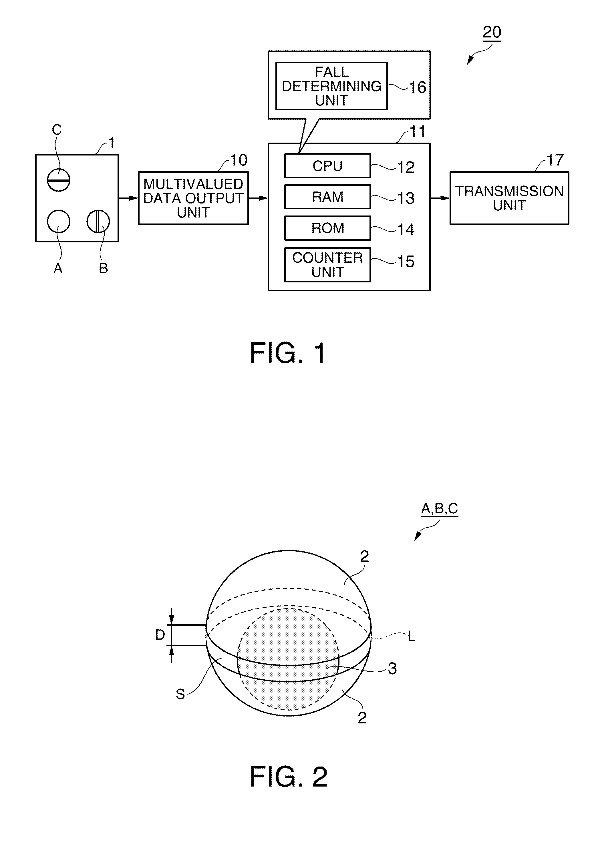
[0029]Hereinafter, a first embodiment of the invention will be described with reference to the accompanying drawings. FIG. 1 is a block diagram illustrating the configuration of a fall detecting device 20 according to the first embodiment.

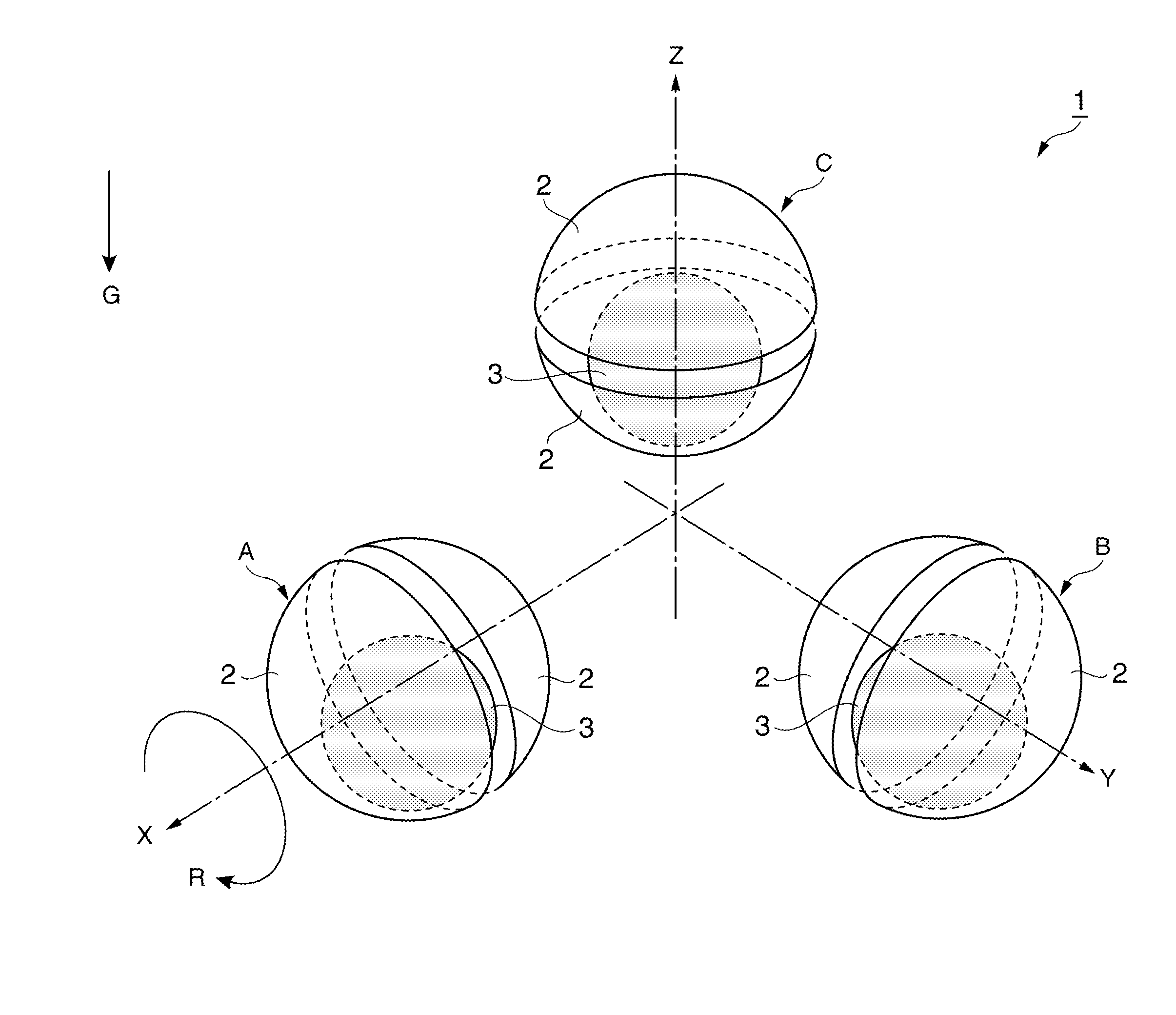
[0030]A detector unit 1 includes tilt sensors A, B, and C. An electrical-connection state of each of tilt sensors A, B, and C is switched between an electrically-connected state (hereinafter, referred to as “ON” state) and an electrically-disconnected state (hereinafter, referred to as “OFF” state) due to a variation in posture of the detector unit 1.

[0031]A multivalued data output unit 10 shown in FIG. 1 is formed of an electronic circuit. The multivalued data output unit 10 acquires the electrical-connection state of tilt sensors A, B, and C of the detector unit 1 as two-valued data having two steps of ON and OFF, converts the electrical-connection state into multivalued data having four steps of 0, 1, 2, and 3, on the basis of the ratio of an ON...

second embodiment

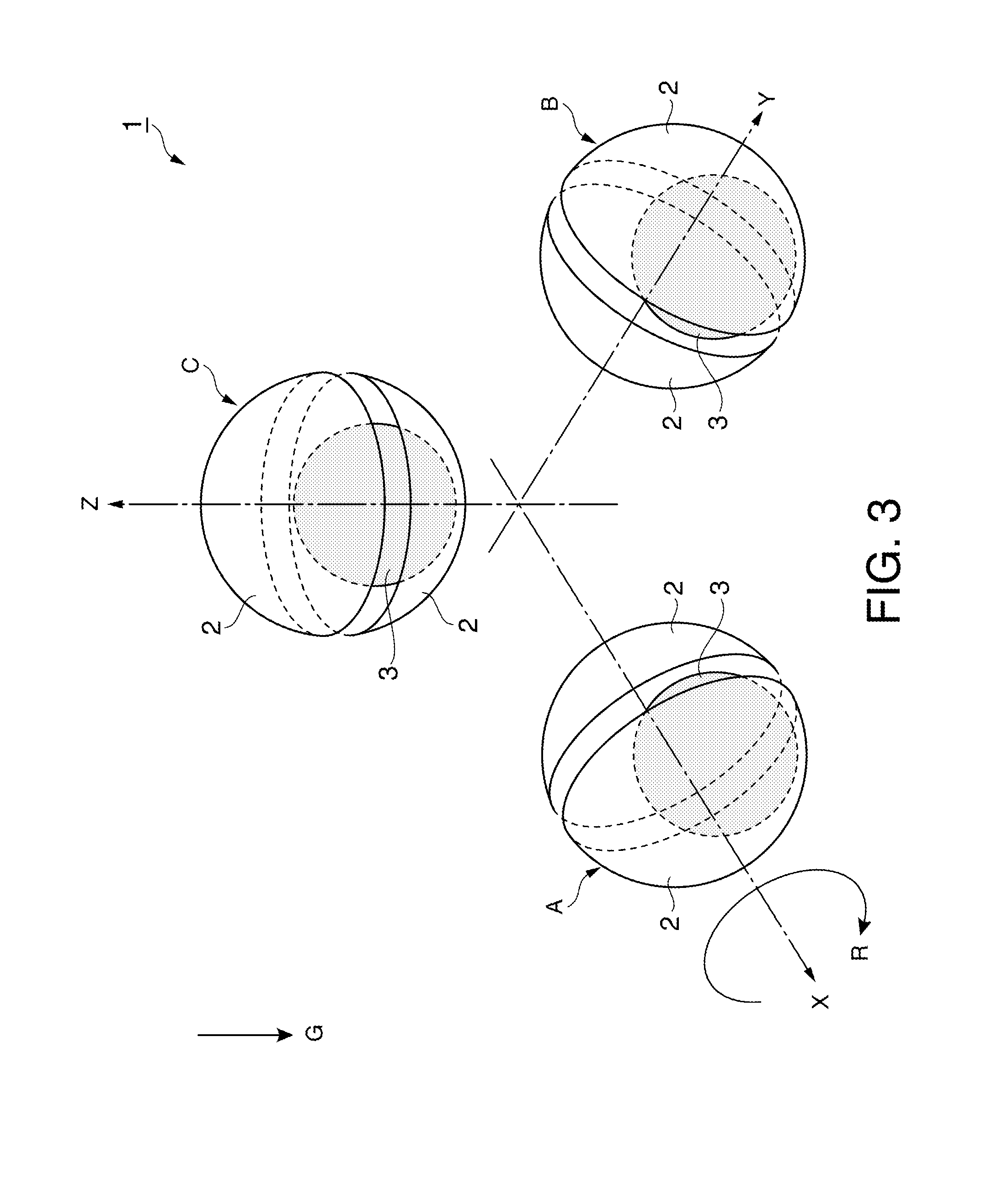
[0071]In a second embodiment of the invention, a method of suppressing an erroneous detection will be described by excluding a case where a wearer wearing the fall detecting device has not fallen but rapidly moves for a long time using multivalued data of the electrical-connection state of tilt sensor C in which the opposing direction of the pair of electrodes 2 is parallel to the vertical direction G shown in FIG. 3 before the fall.

[0072]The graphs shown in FIGS. 8A to 8C are the same as the graphs shown in FIGS. 6A to 6C according to the first embodiment and illustrate the multivalued data of tilt sensors A, B, and C from the normal posture shown in FIG. 3 before the fall to the fallen posture shown in FIG. 4.

[0073]A second time point t2 in FIG. 8C represents a time point when the moving average value of the multivalued data of tilt sensor C in the second period is equal to or less than a second threshold value N2. The second threshold value N2 is experimentally determined and is,...


PUM


Abstract

A fall detecting device includes: a detector unit that includes a plurality of tilt sensors each including a pair of electrodes disposed to oppose each other with the positional relationship therebetween being fixed and a conductor capable of freely moving between the pair of electrodes and changing an electrical-connection state between the pair of electrodes by means of the movement of the conductor resulting from a variation in posture of the pair of electrodes, wherein the plurality of tilt sensors are arranged so that directions in which the pairs of electrodes are opposed to each other are perpendicular to each other; a multivalued data output unit that acquires the electrical-connection states between the pair of electrodes of the plurality of tilt sensors and converts the acquired electrical-connection state into multivalued data on the basis of the ratios of the electrical-connection states in a predetermined first period.

Description

BACKGROUND[0001]1. Technical Field[0002]The present invention relates to a fall detecting device and a fall detecting method.[0003]2. Related Art[0004]A method in which a tilt sensor, an output state of which varies depending on a tilt angle, is attached to a person's body to detect that a solitary elderly person or a construction worker working alone has fallen has been known. For example, JP-A-2008-242704 has proposed a safety confirmation system including an information sending device collecting and sending information detected by the use of a tilt sensor and an information transmitting unit, where a solitary elderly person is assumed to be the wearer wearing the tilt sensor.[0005]In JP-A-2008-242704, the output state of ON or OFF of the tilt sensor is detected as a signal at a predetermined interval and the occurrence of a fall is determined when the period during which the output state of the tilt sensor is OFF is long.[0006]However, in the method described in JP-A-2008-242704,...

Claims


Application Information

Patent Timeline
Patent Type & Authority Applications(United States)
IPC IPC(8): A61B5/11
CPCA61B5/11A61B5/1117G01P15/18G08B21/0446G08B21/043G01C9/06A61B2562/0219
Inventor MASUZAWA, TOSHIHIRO
Owner SEIKO EPSON CORP
Why Eureka
Try Eureka