Control device, robot, and robot system

a control device and robot technology, applied in the direction of programmed manipulators, programme control, instruments, etc., can solve the problem of difficulty in improving the detection precision of force sensors, and achieve the effect of shortening the cycle tim

Inactive Publication Date: 2018-05-10
SEIKO EPSON CORP
View PDF4 Cites 8 Cited by
  • Summary
  • Abstract
  • Description
  • Claims
  • Application Information

AI Technical Summary

Benefits of technology

[0039]In the robot system according to the aspect of the invention, it is possible to shorten the cycle time unde...

Problems solved by technology

However, when a speed of the robot arm is fast, there is a problem that an influence of vibration associated with mov...

Method used


Image

  • Control device, robot, and robot system
  • Control device, robot, and robot system
  • Control device, robot, and robot system

Examples


first embodiment

Robot System

[0051]First, a first embodiment of the invention will be described.

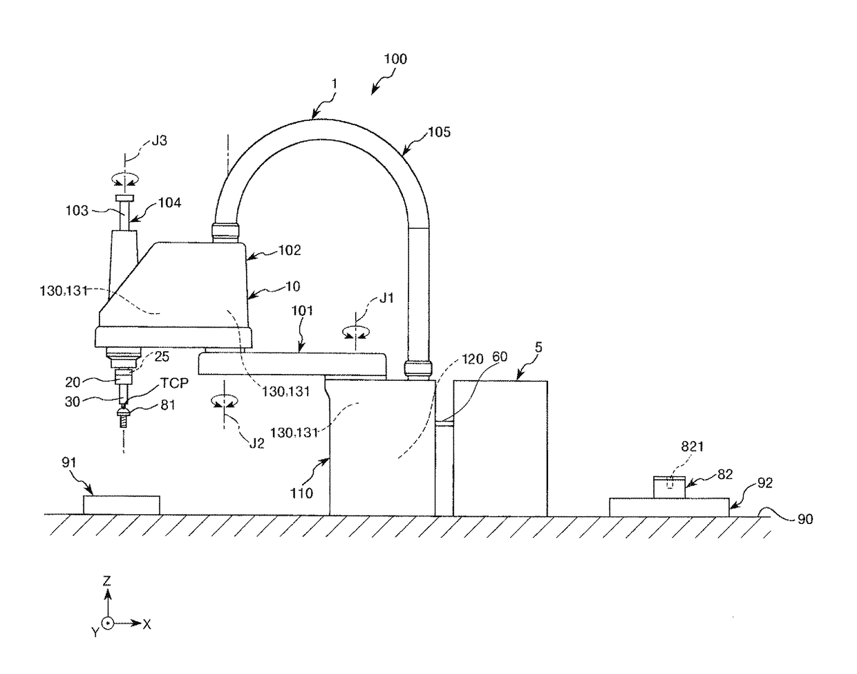
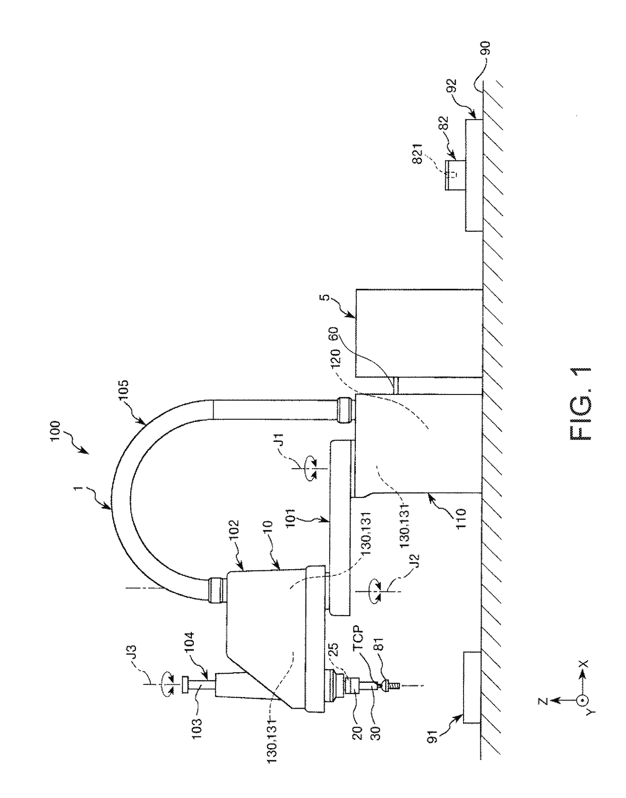
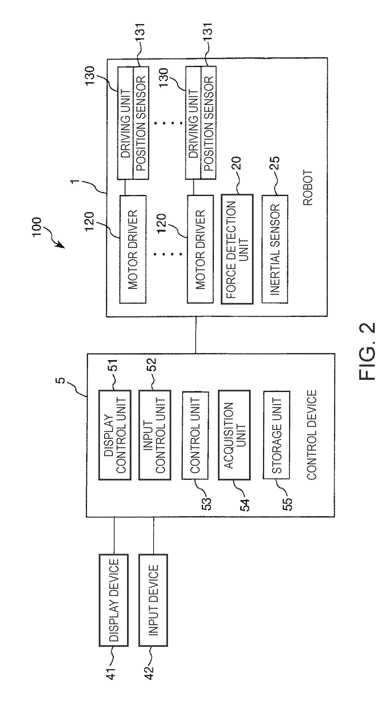
[0052]FIG. 1 is a schematic side view illustrating a robot system according to a first embodiment of the invention. FIG. 2 is a diagram illustrating a system configuration of the robot system illustrated in FIG. 1. Hereinafter, in FIG. 1, the upper side is referred to as an “upper” and the lower side is referred to as a “lower” to facilitate the description. In FIG. 1, the base side is referred to as a “base end” and an opposite side (an end effector side) is referred to as a “tip end”. In FIG. 1, X, Y, and Z axes are illustrated as three axes perpendicular to each other to facilitate the description. Hereinafter, a direction parallel to the X axis referred to as an “X axis direction”, a direction parallel to the Y axis is referred to as a “Y axis direction”, and a direction parallel to the Z axis is referred to as a “Z axis direction”. Hereinafter, a tip end side of each arrow illustrated in the drawing ...

second embodiment

[0127]Next, a second embodiment of the invention will be described.

[0128]FIG. 5 is a schematic side view illustrating a robot system according to a second embodiment of the invention. FIG. 6 is a diagram illustrating an example of a target trajectory of a robot illustrated in FIG. 5. FIG. 7 is a flowchart illustrating a work of the robot illustrated in FIG. 5. FIG. 8 is a schematic diagram illustrating an attitude of an end effector in step S24 of FIG. 7. FIG. 9 is a schematic diagram illustrating an attitude of the end effector in step S25 of FIG. 7.

[0129]In the following description, differences between the present embodiment and the above-described embodiment will be mainly described. The same factors will not be described.

[0130]A robot 1A included in a robot system 100A illustrated in FIG. 5 is a so-called six-axis vertically articulated robot. The robot 1A includes a base stand 110 and the robot arm 10A.

[0131]As illustrated in FIG. 6, the robot arm 10A includes a first arm 11 (...


PUM


Abstract

A control device includes a processor that is configured to execute computer-executable instructions so as to control a robot that includes a robot arm including a force detector, wherein the processor is configured to reset the force detector after moving the robot arm at a first speed, and subsequently moves the robot arm at a second speed faster than the first speed and performs force control based on an output from the force detection unit.

Description

BACKGROUND1. Technical Field[0001]The present invention relates to a control device, a robot, and a robot system.2. Related Art[0002]In the related art, industrial robots including robot arms and end effectors mounted on tip ends of the robot arms have been developed.[0003]As such a robot, for example, JP-A-2015-182164 discloses a robot that includes a robot arm, a force sensor, and a control unit controlling an operation of the robot arm. In the robot, the control unit performs force control based on a detection result from the force sensor.[0004]In the robot disclosed in JP-A-2015-182164, initialization of the force sensor is performed to improve detection precision of the force sensor. Further, in the robot disclosed in JP-A-2015-182164, to shorten a cycle time, the above-described initialization of the force sensor is performed while the robot arm is moving at a uniform speed.[0005]However, in the robot including the control unit disclosed in JP-A-2015-182164, the cycle time can...

Claims


Application Information

Patent Timeline
IPC IPC(8): G05B19/401B25J13/08B25J9/16
CPCG05B19/401B25J13/085B25J9/1694B25J9/1692G05B2219/39529G05B2219/45064G05B2219/45091B25J9/1664B25J19/02G05B2219/39323
Inventor SHIMODAIRA, YASUHIROUEDA, JUNYA
Owner SEIKO EPSON CORP
Why Eureka
Try Eureka