Modular electrical distribution system for a building

a technology for modular electrical distribution and building, applied in the direction of substation/switching arrangement casing, connection contact member material, coupling device connection, etc., can solve the problems of incompatibility of current systems and non-residential buildings, inability to easily interconnect competing systems, and labor-intensive wiring practices

Inactive Publication Date: 2009-02-26
HAWORTH SPA
View PDF99 Cites 56 Cited by
  • Summary
  • Abstract
  • Description
  • Claims
  • Application Information

AI Technical Summary

Problems solved by technology

As described above, the wiring practices for a non-residential building are currently labor-intensive wherein it is desirable to reduce the complexity of this wiring process.
It is believed that these current systems are not compatible with each other wherein one system is provided to develop the lighting circuits and the other system is used to develop power supply receptacles throughout the interior building spaces.
These office furniture power systems usually embody proprietary designs developed by major furniture system manufacturers and as such, these competing systems are not designed to be easily interconnected with each other.
These power systems are more complex than manufactured cable systems in that the only hard wire connection typically is at the point where the system connection is made to the building wiring such as at the power panel.
The above modular systems provide advantages over the most basic hard wiring process, but also do have disadvantages associated therewith which limits the scope of application within a single building structure.
If the order amounts are inadequate, later reorders can take several weeks to obtain which may unacceptably delay building construction.
It is not practical for a distributor to stock even a full range of products for a single brand of such systems because of the different types of systems, i.e. lighting versus power receptacles, and the numerous parts required for each of the three different voltage versions.
However, such products also are proprietary products, or the result of proprietary development such that any single power distribution system typically is not open-sourced but instead is developed and manufactured by or for a specific manufacturer.
Further, the various system designs do not typically anticipate usage of such power systems outside of a furniture or office environment such that the power systems typically are limited to 120 volt applications.

Method used


Image

  • Modular electrical distribution system for a building
  • Modular electrical distribution system for a building
  • Modular electrical distribution system for a building

Examples


Embodiment Construction

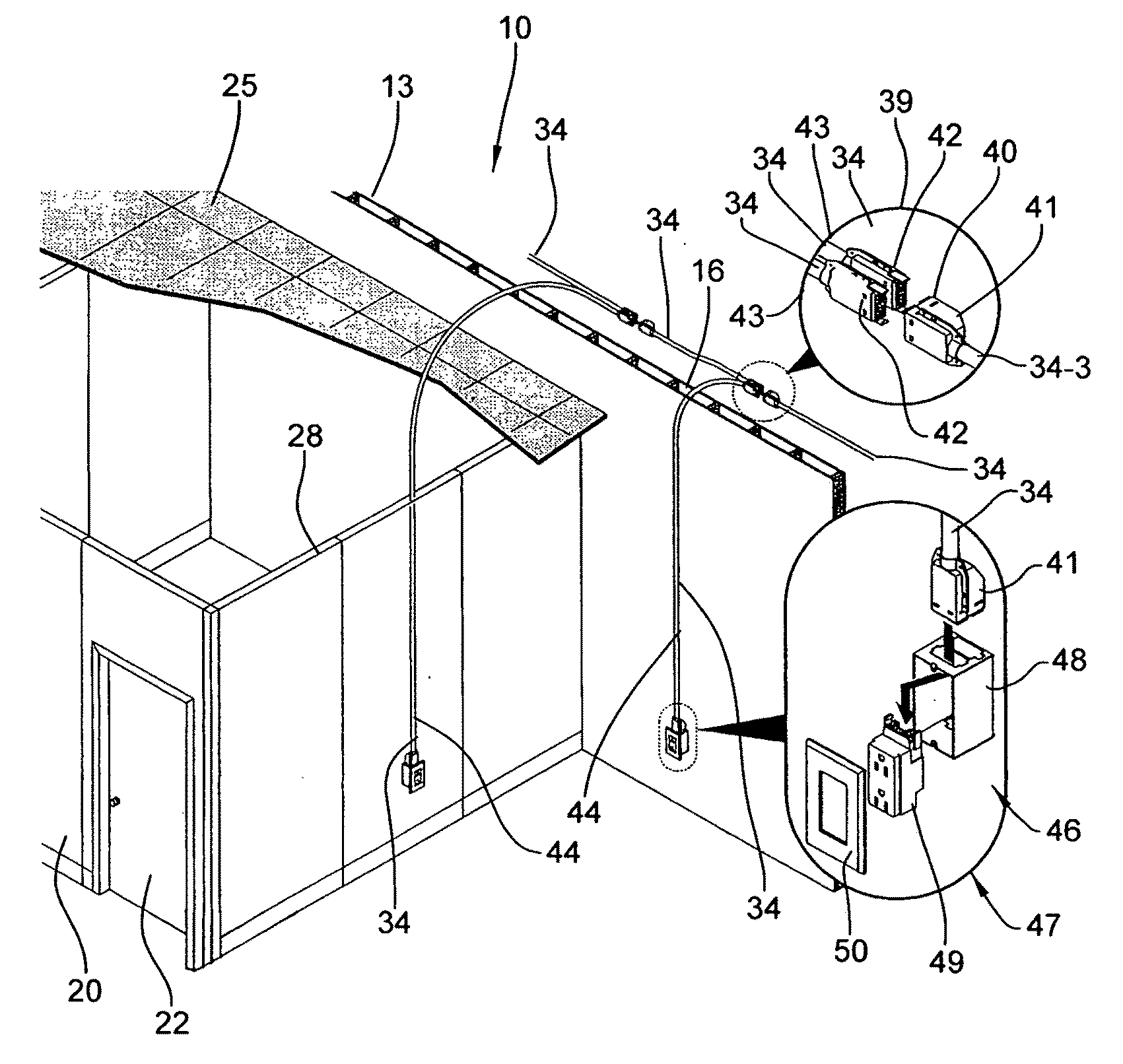
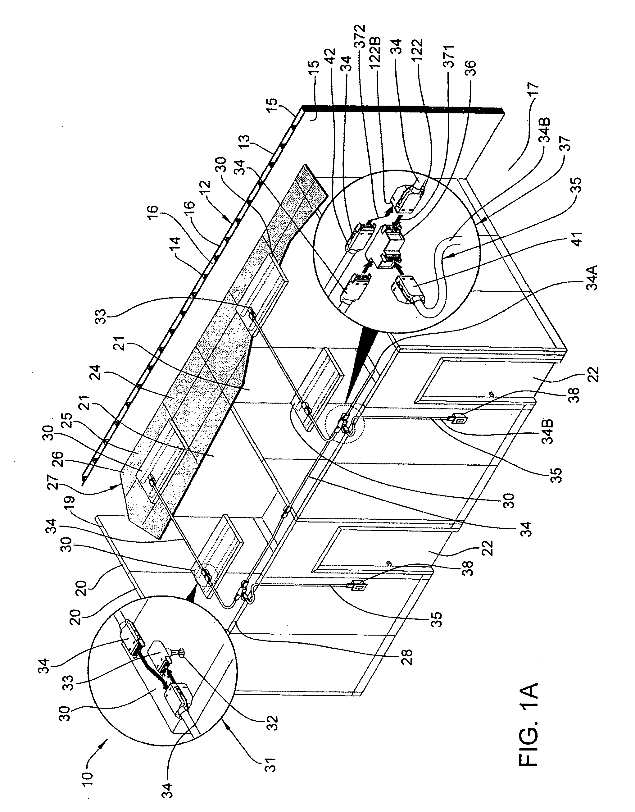
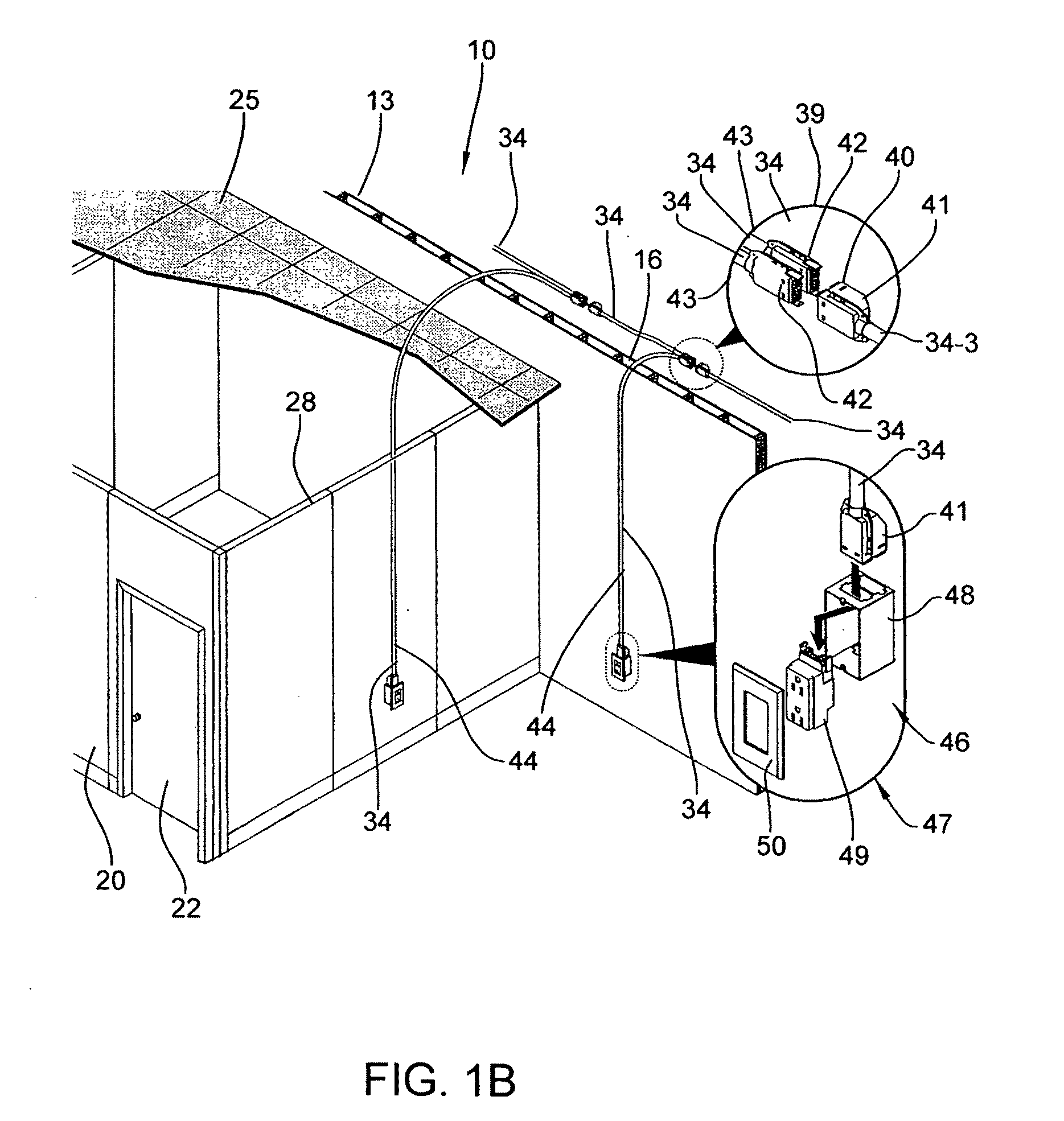
[0175]The invention relates to a universal modular electrical distribution system 10 as illustrated in various configurations in FIGS. 1A-1B and 2-4. The power distribution system 10 has various components and is readily adaptable to multiple applications in non-residential buildings and other similar structures as previously described above. While primarily developed for non-residential applications, the system also could be used in its present form or adapted, if necessary, for residential applications as the need warrants.

I. Overview

[0176]The universal power distribution system 10 of the invention overcomes disadvantages associated with the existing systems described above and is intended to be “universally” adaptable for use to not only supply power to lighting circuits, but also to building-wall receptacle circuits, modular space-dividing office furniture, raised flooring and other building structures.

[0177]Generally as to non-residential buildings, such buildings can be any co...


PUM


Abstract

A universal power distribution system is provided for routing electrical circuits within a building structure to comprehensively provide electrical power to the building in ceiling configurations, wall-mounted configurations, raised floor configurations and in office furniture configurations. The system components for all of these configurations have common plug connectors that are engagable with each other so as to be readily usable in a wide variety of applications. The system is readily adaptable to form virtually any conventional circuit configuration found within conventional hard-wired systems yet is formed simply through the routing of the cables through the building cavities and interconnection is accomplished merely by plugging components together rather than through labor-intensive manual wiring.

Description

CROSS-REFERENCE TO RELATED APPLICATION[0001]This application claims the benefit of U.S. Provisional Application Ser. No. 60 / 964,198, filed Aug. 9, 2007, which is incorporated herein by reference in its entirety.FIELD OF THE INVENTION[0002]The invention relates to a universal modular electrical distribution system for a building and, more particularly, to a system having modular components that are inner-connectable to supply power to lighting and power receptacles.BACKGROUND OF THE INVENTION[0003]In non-residential buildings, such buildings have various sizes dedicated to various uses such as for offices, retail and manufacturing. These buildings typically define relatively large open spaces within the interior thereof that are then outfitted with various interior structures. For office buildings, such interior structures may be space-dividing wall panels that subdivide the open office areas into smaller rooms or work stations. For retail spaces, the open interior building spaces ma...

Claims


Application Information

Patent Timeline
Patent Type & Authority Applications(United States)
IPC IPC(8): H02B1/04
CPCH01R25/006H02G3/38H02G3/00H01R25/16
Inventor JOHNSON, ROSSWILSON, HAROLD
Owner HAWORTH SPA
Why Eureka
Try Eureka