Liquid-cooled grounded heatsink for diode rectifier system

Inactive Publication Date: 2009-02-26
GENERAL ELECTRIC CO
View PDF32 Cites 24 Cited by
  • Summary
  • Abstract
  • Description
  • Claims
  • Application Information

AI Technical Summary

Problems solved by technology

Numerous pieces of soldered copper pipe, all of which may potentially form leaks at the connection points, are used to supply the liquid coolant.
Moreover, the presence of elevated voltages on wetted surfaces drives ions from the wetted surface into the water, which increases the rate of corrosion.
However, the refurbishing merely restores the rectifier to the previous condition and all of the weaknesses of the design are maintained, e.g

Method used


Image

  • Liquid-cooled grounded heatsink for diode rectifier system
  • Liquid-cooled grounded heatsink for diode rectifier system
  • Liquid-cooled grounded heatsink for diode rectifier system

Examples


Embodiment Construction

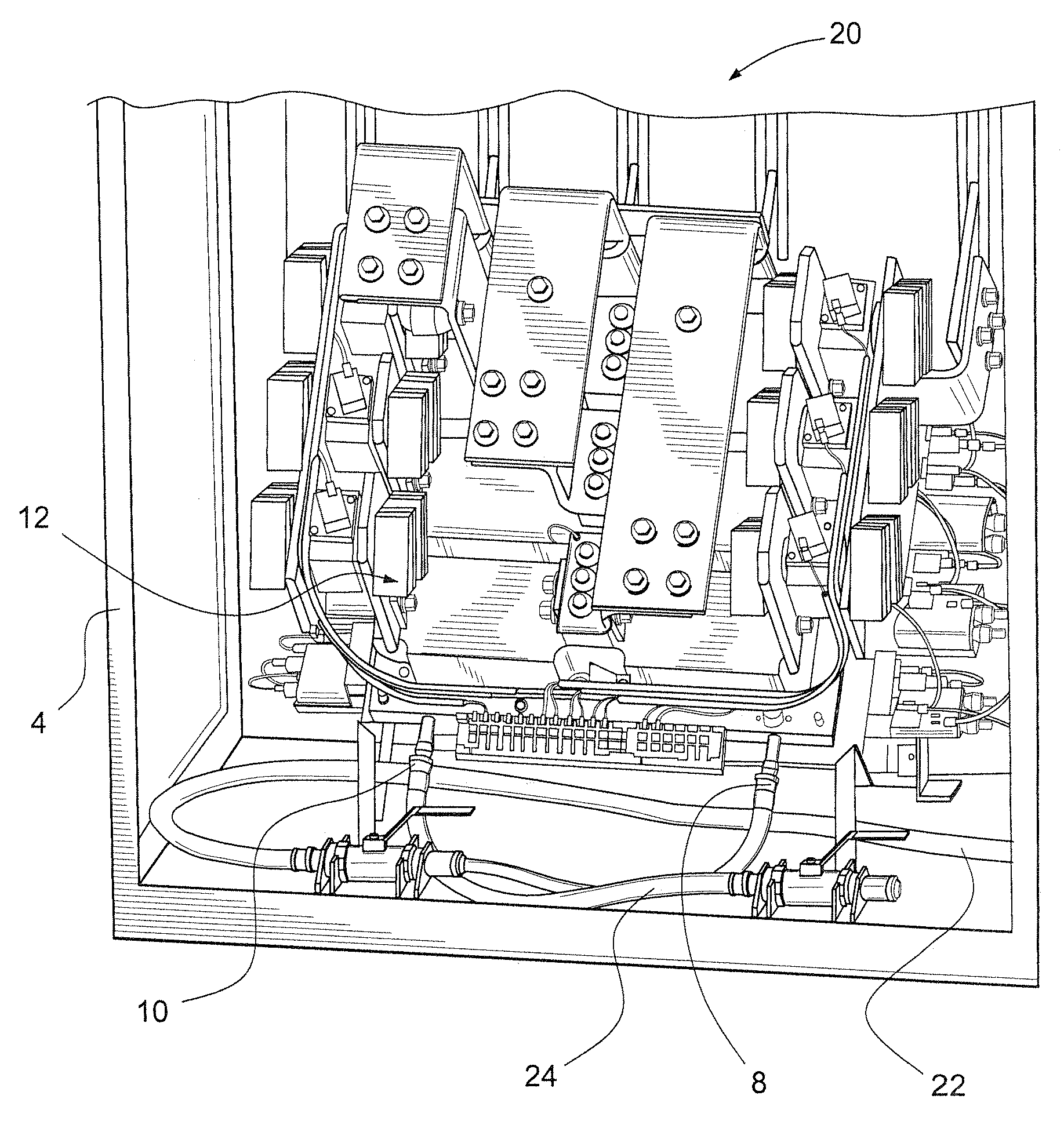
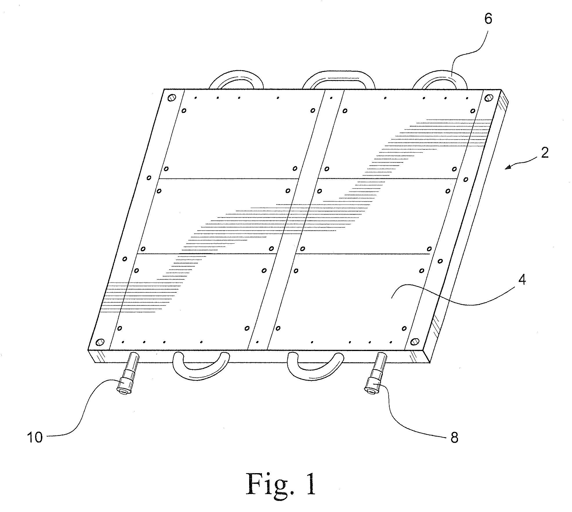
[0010]Referring to FIG. 1, a liquid-cooled grounded heatsink diode rectifier system 2 for generator excitation includes a heatsink 4 and a coolant tube 6 configured to carry liquid coolant throughout the heatsink 4. The coolant tube 6 includes a coolant inlet 8 and a coolant outlet 10.

[0011]The coolant tube 6 may be a single pre-formed stainless steel tube that is embedded into the heatsink 4. It should be appreciated, however, that other materials may be used for the coolant tube 6 and the heatsink 4. The heatsink 4 is configured to be large enough to hold, at least, six diode modules (FIG. 2) while only having the two coolant connections, the coolant inlet 8 and the coolant outlet 10.

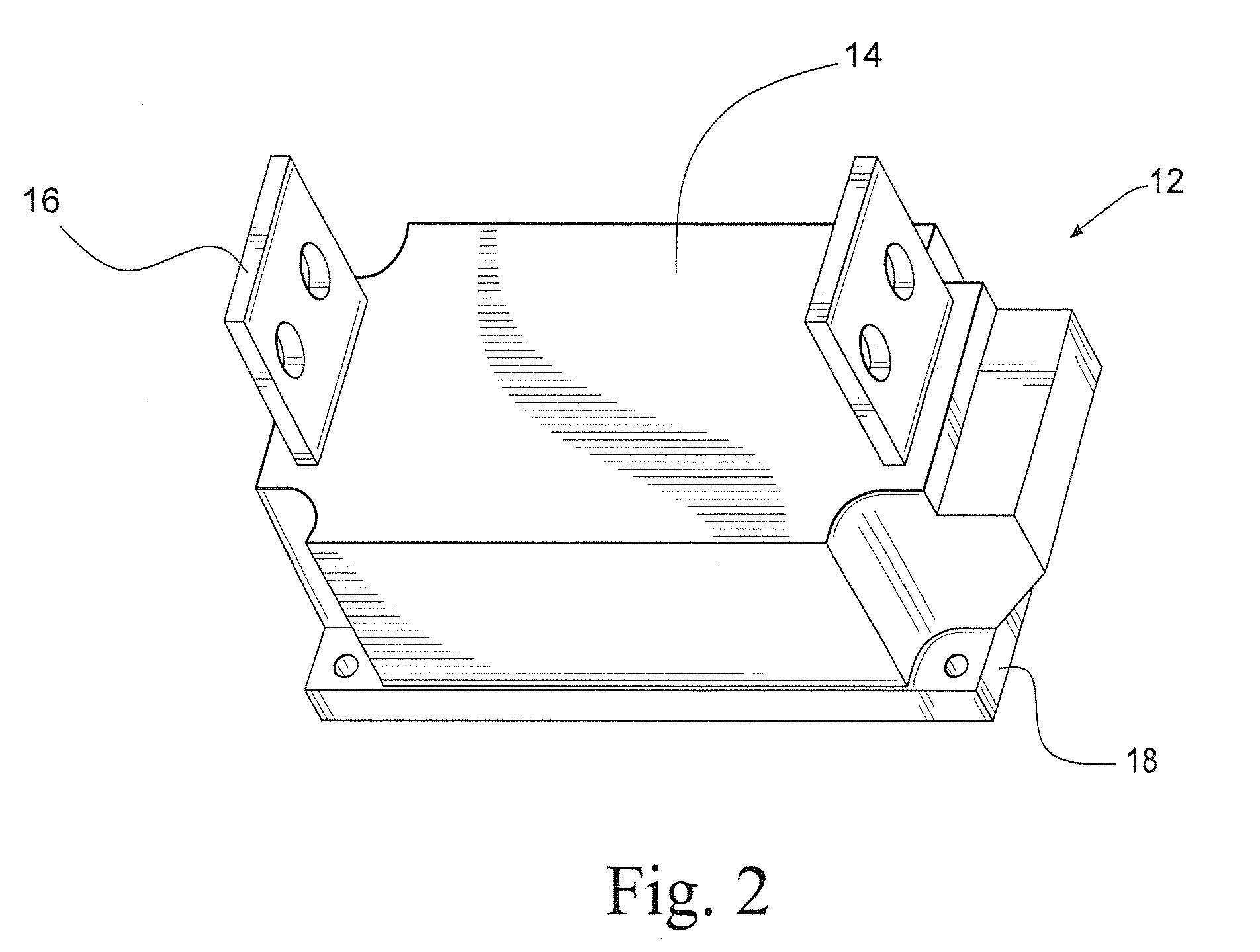
[0012]Referring to FIG. 2, a diode module 12 includes a diode 14 and a diode clamp 16. The diode module 12 also includes an insulating layer 18. The internal insulating layer 18 of the diode module 12 may be made of, for example, alumina or aluminum nitride. The internal insulating layer 18 keeps the ...


PUM


Abstract

A diode rectifier system for generator excitation includes a plurality of diode modules mounted on a heatsink and a coolant tube provided in the heatsink. The heatsink is electrically grounded. A method of cooling a diode rectifier system for generator excitation comprises providing a flow of liquid coolant in the coolant tube and electrically grounding the heatsink.

Description

CROSS REFERENCE TO RELATED APPLICATION[0001]This application claims priority to U.S. Application 60 / 957,251, filed Aug. 22, 2007, the entire content of which is incorporated herein by reference.BACKGROUND OF THE INVENTION[0002]The present invention relates to a liquid-cooled grounded heatsink diode rectifier system for generator excitation applications.[0003]A diode rectifier system may be used to convert alternating current (AC) to direct current (DC). In order to function properly, the heat generated by the diode rectifier system must be removed, for example to a heatsink. Current rectifier systems for generator excitation applications are known which include a plurality of coolant hoses, for example 20 or more, and a plurality of liquid-cooled heatsinks, for example, either 4 or 16. Numerous pieces of soldered copper pipe, all of which may potentially form leaks at the connection points, are used to supply the liquid coolant. Coolant, for example water, is circulated through the ...

Claims


Application Information

Patent Timeline
IPC IPC(8): H05K7/20H02K11/04
CPCH01L23/473H02K9/19H02K11/046H05K7/20927H01L2924/0002H01L2924/00H02K11/05H05K7/20
Inventor CASTEEL, JORDAN B.MONCLOVA, PEDROBITTNER, JOHN E.LINDHOLM, BRIAN E.FREEMAN, MELISSA
Owner GENERAL ELECTRIC CO
Why Eureka
Try Eureka