
Fixing device, image forming apparatus using the fixing device, and temperature control method for the fixing device

Inactive Publication Date: 2009-02-26
RICOH KK
View PDF18 Cites 28 Cited by
  • Summary
  • Abstract
  • Description
  • Claims
  • Application Information

AI Technical Summary

Benefits of technology

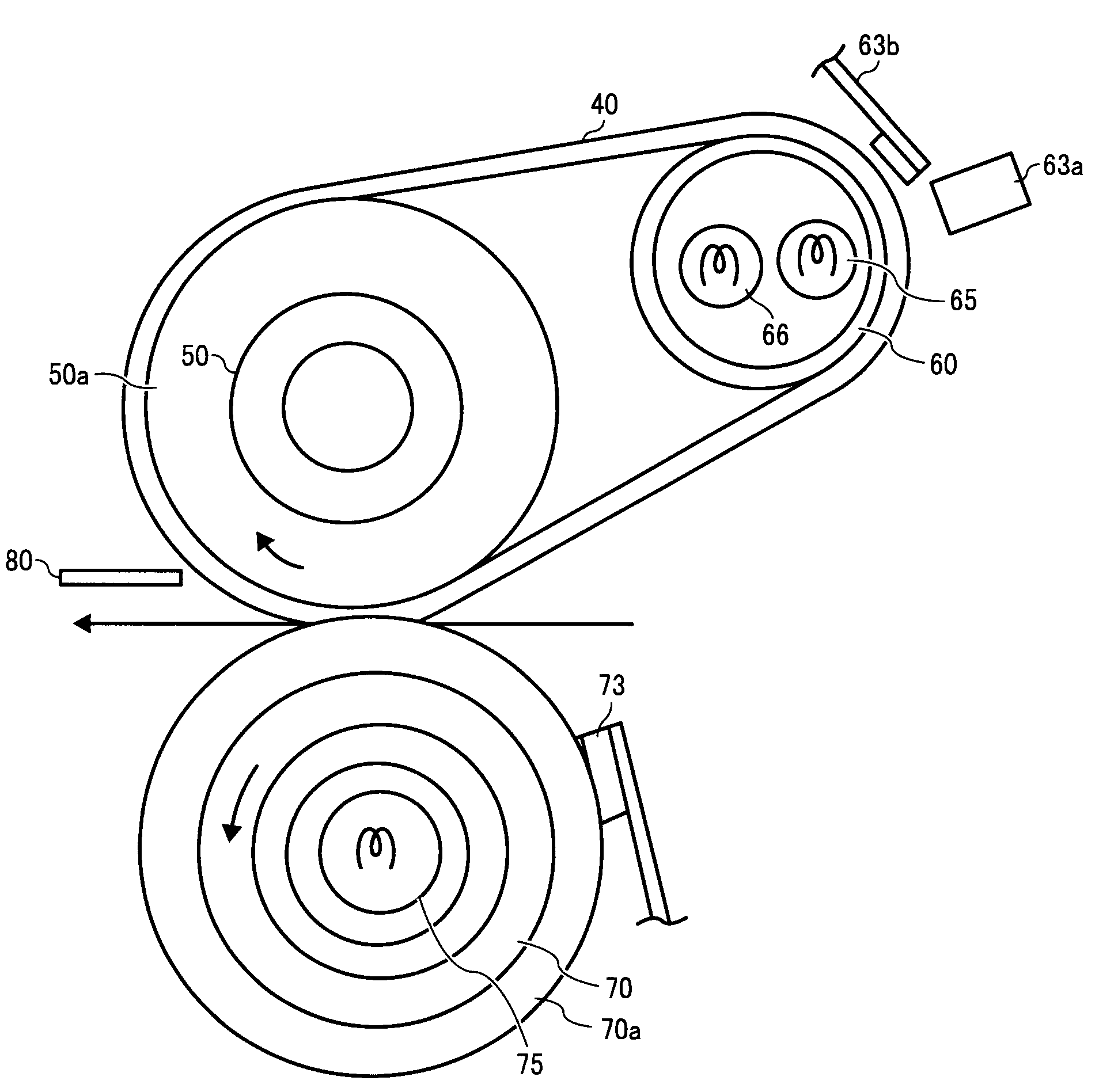
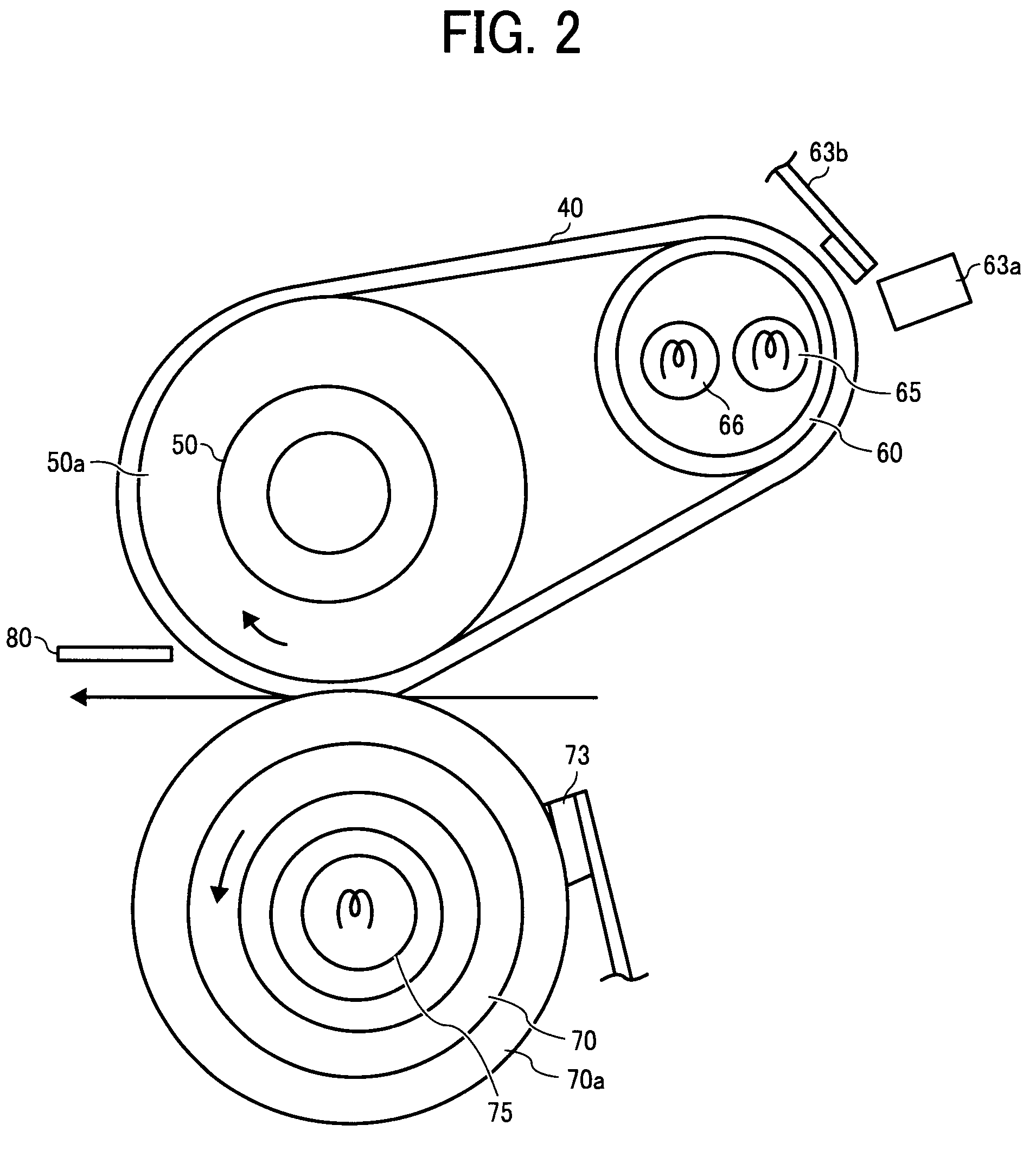
[0012]Described herein is a novel fixing device that includes a fixing roller, a heat roller including a first heat source and a second heat source, with the first heat source being a first halogen heater to mainly irradiate a center portion of a paper feed area and the second heat source being a second halogen heater to mainly irradiate an end portion of the paper feed area, a fixing belt stretched around the fixing roller and the heat roller, a pressure roller including a pressure heat source being a third halogen heater and rotating in press contact with the fixing roller, a first temperature detector to detect a temperature of the center portion of the paper feed area on the fixing belt, which is used to control activation of the first heat source based on a set temperature of the center portion, a second temperature detector to detect a temperature of the end portion of the paper feed area on the fixing belt or a temperature of the fixin

Problems solved by technology

Such a fixing device consumes a large amount of electrical power during operation to heat the paper quickly passing therethrough and compensate for heat loss due to contact with the paper.
The power consumption for fixing is increased in a high-speed image forming apparatus as the number of paper passing through the fixing device per unit time increases.
At the same time, however, a maximum power consumption specified for the image forming apparatus depends on a power supply situation, and tends not to provide sufficient electrical power under environmental and use-paper constraints particularly like those in effect in Japan or in North America.
When the power supply is insufficient, the temperature of the fixing roller included in the fixing device cannot be maintained at a set temperature and declines during paper feed.
In order to correct this tendency, the fixing device in the typical high-speed image forming apparatus consumes the maximum allowable amount of electrical power.
Also, in a recent mainstream configuration in which a heater of the fixing device is turned off in a standby mode to save energy, the fixing roller needs to be rapidly heated to the set temperature, which also adds to overall electrical power requirements.
An additional problem is that the heater is started using electrical power including the electrical power saved by stopping other operations performed in the image forming apparatus.
Consequently, there is a large difference between the heater power consumption while starting the heater and the heater power consumption during paper feed, which again adds to overall electrical power requirements.
However, in practical usage, allowable electrical power for the fixing device varies according to the mode of operation, and as such the heaters are unable to respond to such varying statuses simply by controlling their duty cycle.
Therefore, such a fixing device is not useful in an image forming apparatus whose productivity is determined by the fixing ability maintained according to the electrical power.
In this case, however, even with the heater wattage at full activation for the center heater, less than the allowable electrical power for the fixing device is being used.
Also, heat transfer through the heat roller from the end portion to the center portion stops by turning off the end heater, and therefore the temperature of the center portion may not be raised to the proper temperature.
By contrast, when the heater wattage for full activation of the center heater is equal to the allowable electrical power for the fixing device, the center heater cannot be efficiently activated in a mode in which the allowable electrical power for the fixing device is deliberately reduced as an energy-saving measure.

Method used


Image

  • Fixing device, image forming apparatus using the fixing device, and temperature control method for the fixing device
  • Fixing device, image forming apparatus using the fixing device, and temperature control method for the fixing device
  • Fixing device, image forming apparatus using the fixing device, and temperature control method for the fixing device

Examples


Embodiment Construction

[0028]In describing preferred embodiments illustrated in the drawings, specific terminology is employed for the sake of clarity. However, the disclosure of this patent specification is not intended to be limited to the specific terminology so selected and it is to be understood that each specific element includes all technical equivalents that operate in a similar manner and achieve a similar result.

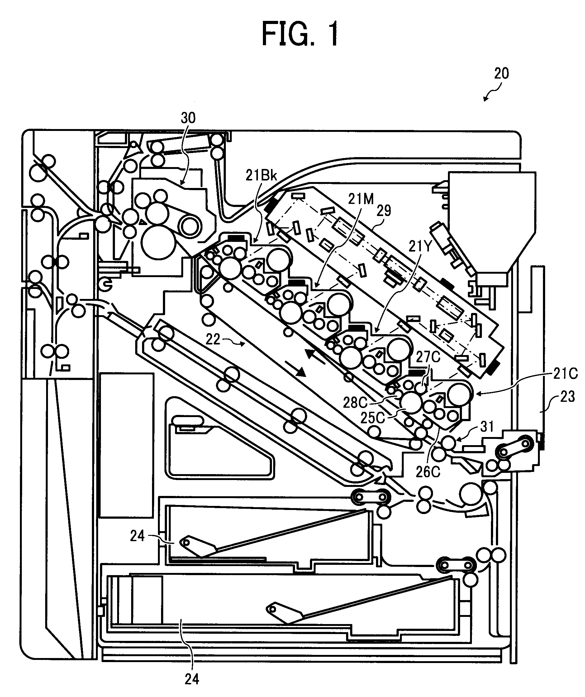
[0029]FIG. 1 is a schematic diagram illustrating a configuration of an image forming apparatus according to an embodiment of the present invention. In FIG. 1, an image forming apparatus 20 includes image forming devices 21C, 21Y, 21M, and 21Bk that form images of different colors corresponding to an original image, a transfer device 22 disposed facing the image forming devices 21C, 21Y, 21M, and 21Bk, a manual feed tray 23, paper feed cassettes 24, and registration rollers 31 that serve as sheet medium supply units to supply various sheet media to transfer areas formed between the transf...


PUM


Abstract

A fixing device, an image forming apparatus using the fixing device, and a temperature control method therefor. The fixing device includes a fixing roller, a heat roller including first and second heat sources, a fixing belt, a pressure roller including a pressure heat source, a first temperature detector, a second temperature detector, and a pressure temperature detector. The heat sources are regularly on and off according to a duty cycle, and at least one of the heat sources is controlled by the duty cycle during paper feed. A wattage of one of the heat sources is added to a wattage of at least one of the other heat sources when the temperature detected by the first or second temperature detector corresponding to the one of the heat sources reaches the set temperature such that a duty ratio of the at least one of the other heat sources is increased.

Description

CROSS-REFERENCE TO RELATED APPLICATIONS[0001]This patent specification is based on and claims priority from Japanese Patent Application No. 2007-216992, filed on Aug. 23, 2007 in the Japan Patent Office, the entire contents of which are hereby incorporated by reference herein.BACKGROUND[0002]1. Field of the Invention[0003]The present invention relates to a fixing device, an image forming apparatus using the fixing device, and a temperature control method for the fixing device.[0004]2. Description of the Related Art[0005]An electrophotographic image forming apparatus, such as a copier, a printer, or a facsimile, generally uses a heat roller fixing device (including a heat belt fixing device) to fix toner attached to paper onto the paper using heat and pressure. Such a fixing device consumes a large amount of electrical power during operation to heat the paper quickly passing therethrough and compensate for heat loss due to contact with the paper. The power consumption for fixing is i...

Claims


Application Information

Patent Timeline
IPC IPC(8): G03G15/20
CPCG03G15/2039G03G2215/2029
Inventor YOSHIKAWA, TAKAHIRO
Owner RICOH KK
Learn More