Pace-adjusting mechanism of an elliptical cross trainer

a technology of elliptical cross trainer and adjusting mechanism, which is applied in the direction of cardiovascular exercise devices, sport apparatus, gymnastic exercise, etc., can solve the problems of not being able to use the pace-adjusting mechanism, and not being able to achieve the pace-adjusting mechanism that is practical and valuable. , to achieve the effect of convenient and practical use and easy to perform the desired adjustmen

a technology of elliptical cross trainer and adjusting mechanism, which is applied in the direction of cardiovascular exercise devices, sport apparatus, gymnastic exercise, etc., can solve the problems of not being able to use the pace-adjusting mechanism, and not being able to achieve the pace-adjusting mechanism that is practical and valuable. , to achieve the effect of convenient and practical use and easy to perform the desired adjustmen

US20090054212A1Inactive Publication Date: 2009-02-26WANG LEAO

Image

  • Pace-adjusting mechanism of an elliptical cross trainer
  • Pace-adjusting mechanism of an elliptical cross trainer
  • Pace-adjusting mechanism of an elliptical cross trainer

Examples


Embodiment Construction

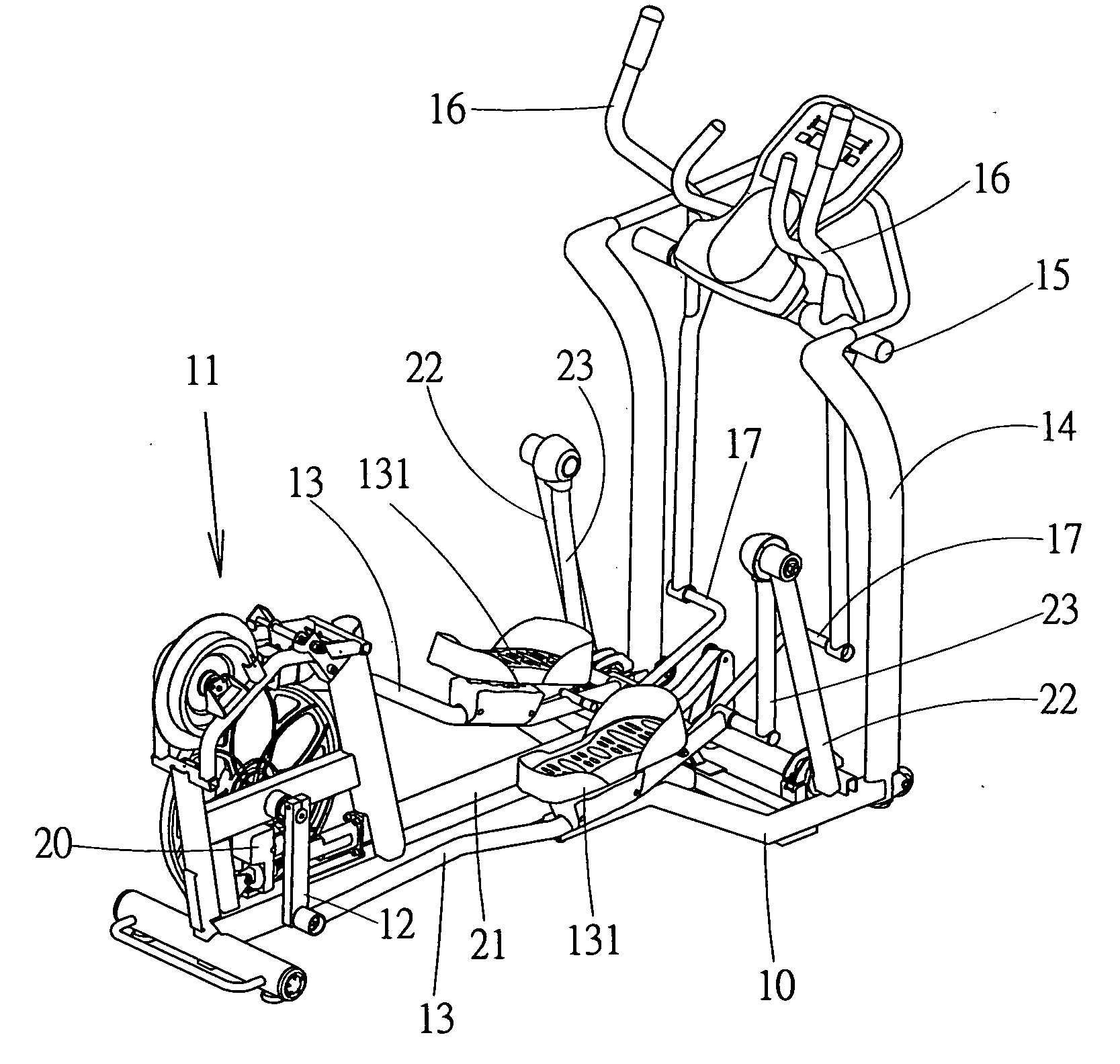
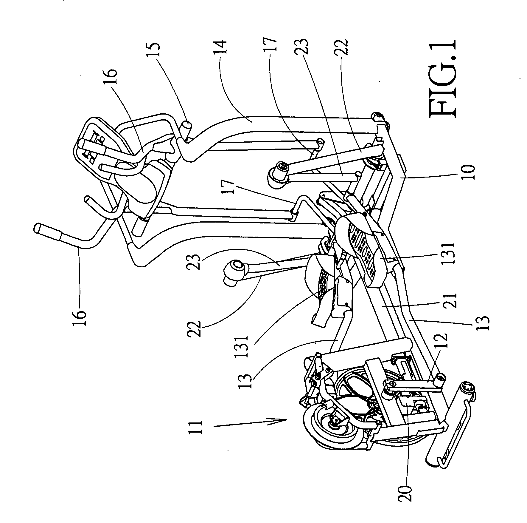
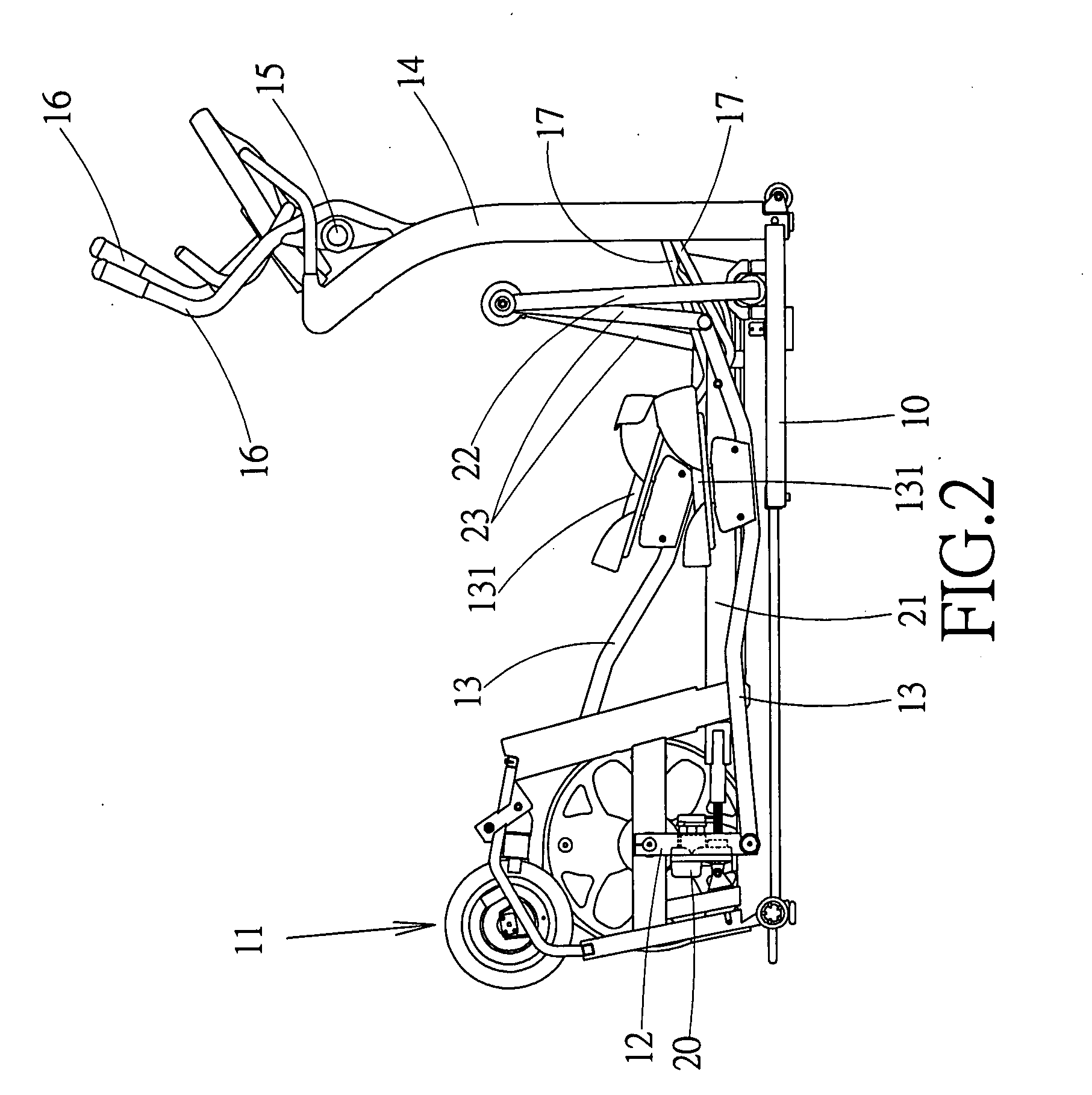
[0013]Referring to FIGS. 1 and 2, a preferred embodiment of the invention includes a frame unit 10 und an electric adjusting motor 20.

[0014]The frame unit 10 has a rear end on which a flywheel transmission unit 11 is placed. The flywheel transmission unit includes a crank 12 at both sides thereof that is pivotally coupled to a corresponding treadle plank 13. The elliptical cross trainer has two upright posts 14 at the front end thereof between which a cross bar 15 is extended. Two handles 16 are pivotally attached to the cross bar 15. A bend 17 is pivotally coupled to a bottom end of the handles 16, respectively. Moreover, the opposing end of the bend 17 is pivotally coupled to a bottom end near the front section of the treadle plank 13. In this way, the components are coupled in such a way that they can be synchronically moved.

[0015]The electric adjusting motor 20 is installed at the bottom of the flywheel transmission unit 11 for driving a telescopic tube 21 in a shift movement. T...


PUM


Abstract

A pace-adjusting mechanism of an elliptical cross trainer having an electric adjusting motor installed at the bottom of a flywheel transmission unit for driving a telescopic tube in displacement. Meanwhile, a w-shaped driven connecting rod and two L-shaped connecting elements are employed to adjust the vertical position of two treadle planks, thereby achieving different exercise paces.

Description

BACKGROUND OF THE INVENTION[0001]1. Fields of the Invention[0002]The invention relates to a pace-adjusting mechanism of an elliptical cross trainer, and more particularly, to a mechanism that can rapidly adjust the movement pace at will.[0003]2. Description of the Related Art[0004]The elliptical cross trainer is so used that the operator's feet can make an elliptical movement path, thereby simulating the real running and walking path. Moreover, the horizontal pace (simulating the movement on a flat ground) and the inclined pace (simulating the uphill and downhill movement) can be changed when the vertical position of the treadles of the elliptical cross trainer changes. This is the main intention of the invention.[0005]U.S. Pat. No. 6,090,013 discloses such a mechanism that employs a plurality of selection holes in treadle planks. By selecting a desired hole in the treadle plank for connection, the coupling angle of the treadle plank can be changed to achieve the above-mentioned pac...

Claims


Application Information

Patent Timeline
26 Feb 2009
Publication
US20090054212A1
IPC
A63B24/00; A63B22/04
CPC
A63B21/225; A63B22/001; A63B2071/025; A63B22/0664; A63B2022/067; A63B22/0015
Inventors
WANG, LEAO