Communication terminal, terminal switching system, and terminal switching method

a terminal switching and communication terminal technology, applied in the field of communication terminals, terminal switching systems, and terminal switching methods, can solve the problems of inability to connect to the user, disadvantageous functionality and operability, and reduced portability of mobile terminals, so as to reduce time loss and eliminate retrying the switching process

Active Publication Date: 2009-02-26
PANASONIC INTELLECTUAL PROPERTY CORP OF AMERICA
View PDF16 Cites 55 Cited by
  • Summary
  • Abstract
  • Description
  • Claims
  • Application Information

AI Technical Summary

Benefits of technology

[0011]With such makeup, the transfer-source terminal determines a transfer-destination terminal according to connectivity information collected by a nearby terminal, thus allowing the transfer-source terminal to select an appropriate transfer-destination terminal from among nearby terminals.
[0013]Herewith, the transfer-source terminal determines a transfer-destination terminal according to information on connectivity with a communication-destination terminal or a server of the network, collected as a result that the nearby terminal performs a communication process, thus allowing the transfer-source terminal to select an appropriate transfer-destination terminal from among nearby terminals.
[0015]Herewith, the transfer-source terminal limits nearby terminals from which connectivity information is acquired, according to terminal information, thus allowing the transfer-source terminal to acquire connectivity information with a small amount of network communication traffic to select a suitable transfer-destination terminal.
[0016]As described above, the present invention allows the user to switch from the communication terminal in communication to a more appropriate communication terminal, eliminates retrying a switching process, and reduces time loss, due to a connection failure after terminal switching or a connection not satisfying the user demands.

Problems solved by technology

However, a mobile terminal is reduced in size and weight for portability, and thus is often disadvantageous in functionality and operability compared to a stationary terminal such as a PC.
Accordingly, a mobile terminal, when actually switching a terminal, may fail to connect a transfer-destination terminal to a communication-destination terminal and needs to try the process again, or may end up with connection undesirable for the user.
That is, network-level connection between a transfer-destination terminal and communication-destination terminal fails due to security-related restrictions in the communication-destination terminal or the network; communication with the same quality as heretofore is not available due to a deficient band of the communication network between a transfer-destination terminal and a communication-destination terminal; and connection between applications fails due to different implementation in spite that a transfer-destination terminal and a communication-destination terminal have the same application-layer protocol.
Consequently, the user undesirably needs to wait longer until a process for switching to a transfer-destination terminal completes.

Method used


Image

  • Communication terminal, terminal switching system, and terminal switching method
  • Communication terminal, terminal switching system, and terminal switching method
  • Communication terminal, terminal switching system, and terminal switching method

Examples


first exemplary embodiment

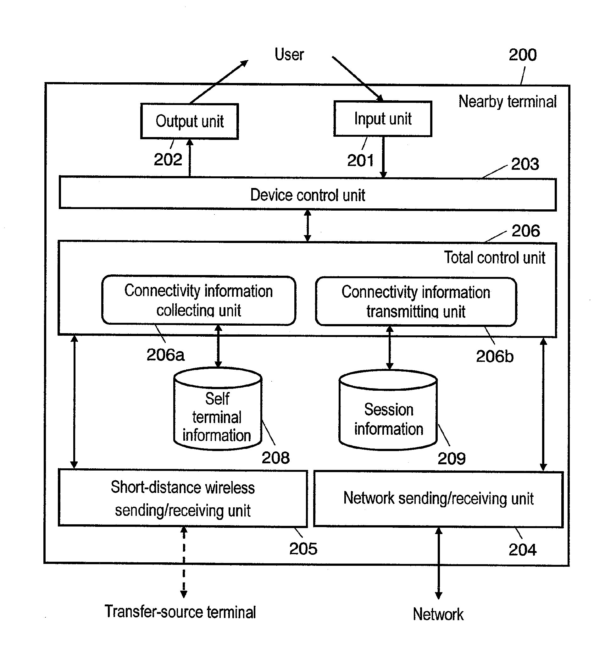
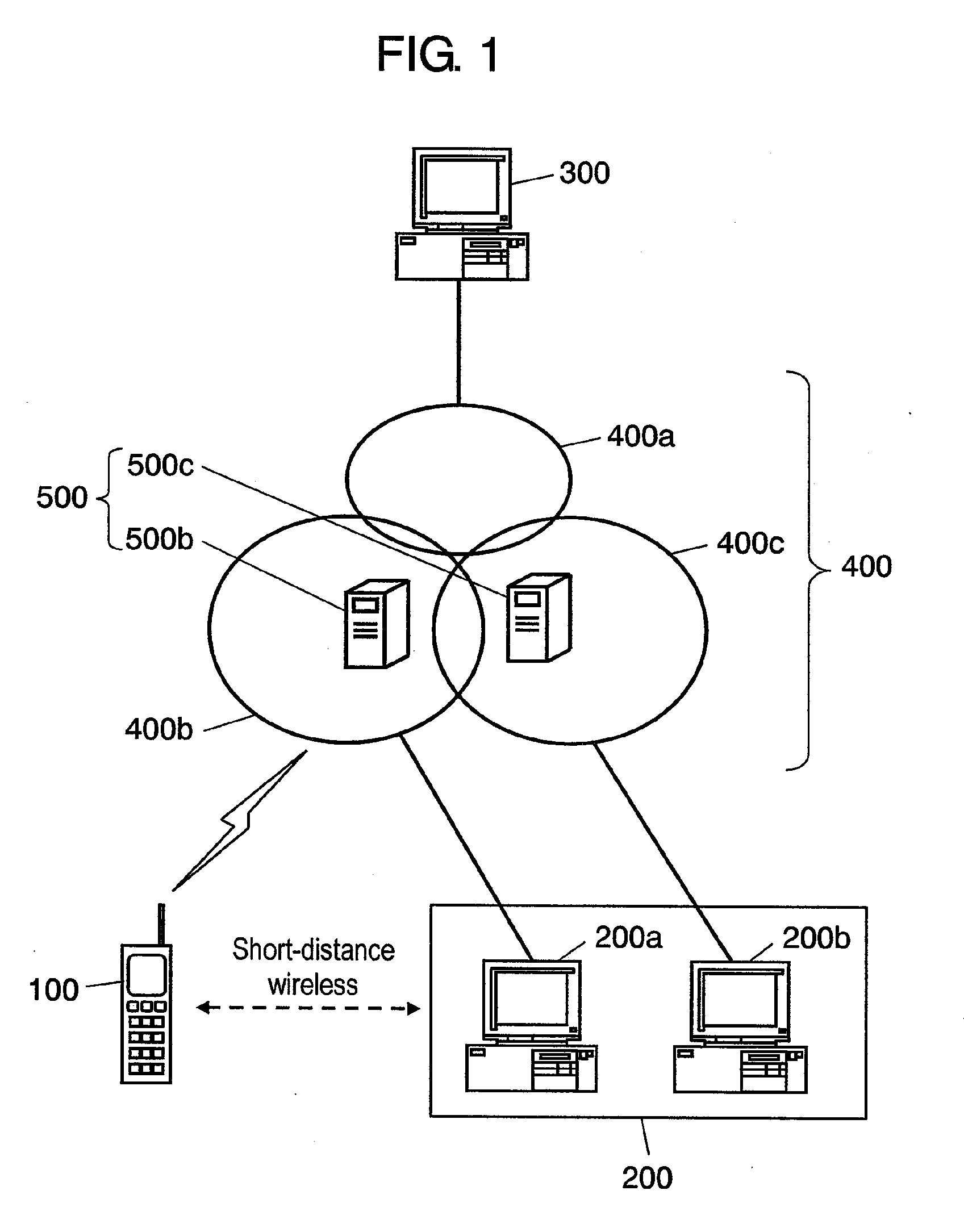
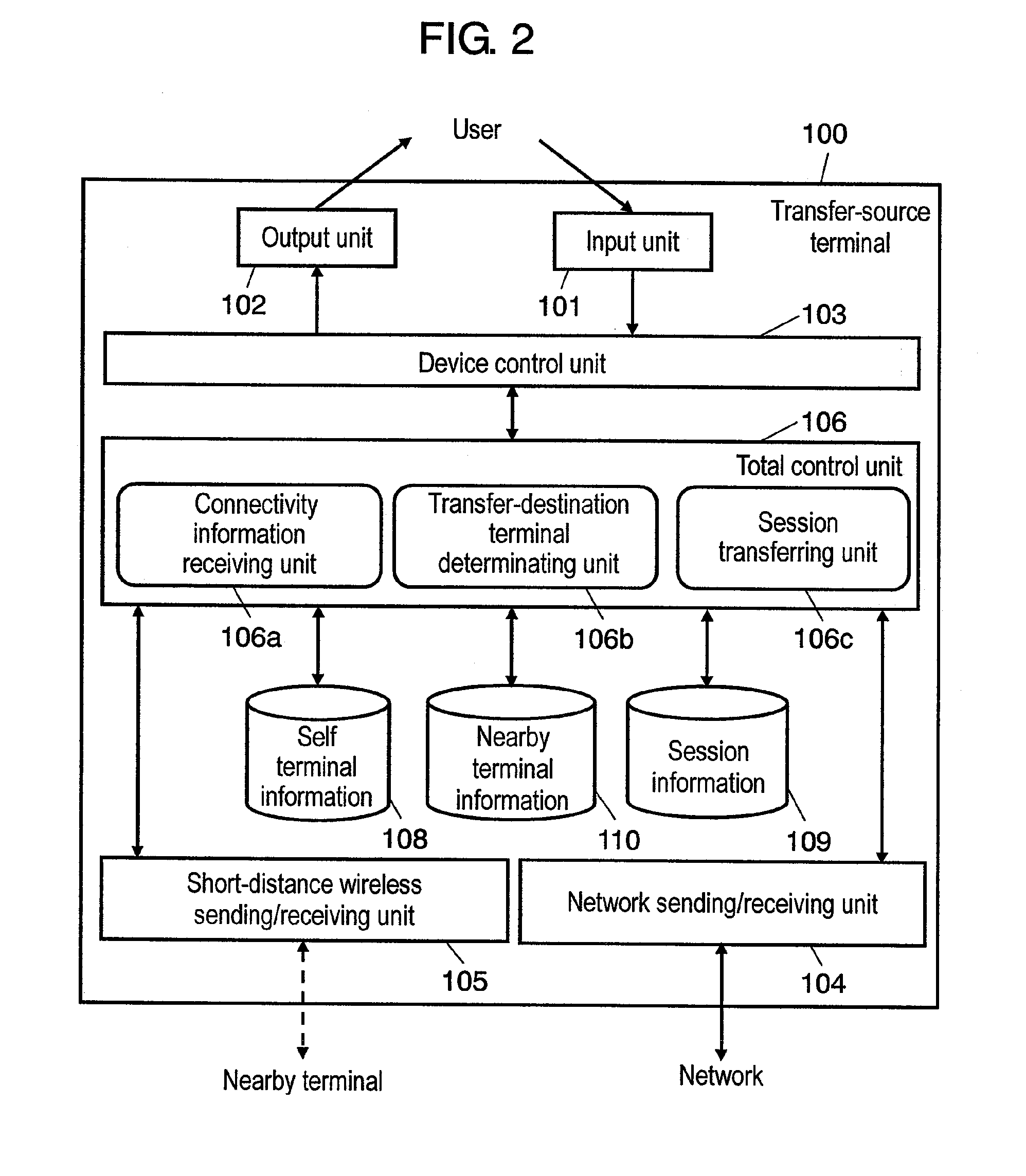
[0061]FIG. 1 illustrates the makeup of a terminal switching system according to the first exemplary embodiment of the present invention.

[0062]As shown in FIG. 1, the terminal switching system according to the first embodiment includes transfer-source terminal 100 connected to second network 400b; communication-destination terminal 300 connected to first network 400a; and nearby terminals 200a, 200b, both positioned in the neighborhood of transfer-source terminal 100, respectively connected to second network 400b and third network 400c. Second network 400b and third network 400c have servers 500b, 500c, respectively therein, that execute procedures such as login, authentication, and billing for network users. Hereinafter, the terminal group in the neighborhood of the user is collectively referred to as nearby terminal 200. First network 400a, second network 400b, and third network 400c are collectively called network 400; server 500b and server 500c, server 500.

[0063]In the first emb...

second exemplary embodiment

[0113]Next, a description is made for a terminal switching system according to the second exemplary embodiment of the present invention.

[0114]The terminal switching method according to the second embodiment is different from the first embodiment in that transfer-source terminal 100 determines a transfer-destination candidate terminal according to terminal information acquired by searching for nearby terminals 200 using short-distance wireless and requests connectivity information after terminal switching only from the transfer-destination candidate terminal.

[0115]FIG. 12 illustrates the makeup of a transfer-source terminal in the terminal switching system according to the second embodiment.

[0116]In FIG. 12, the makeup is different from that of the first embodiment in that total control unit 1206 has terminal information receiving unit 1206a and transfer-destination candidate terminal determinating unit 1206b.

[0117]Terminal information receiving unit 1206a receives terminal informat...


PUM


Abstract

A transfer-source terminal, a communication-destination terminal, and a nearby terminal existing in the neighborhood of transfer-source terminal are provided. The nearby terminal collects connectivity information for monitoring connectivity after terminal switching by performing a communication process with the communication-destination terminal, and transmits the connectivity information collected to the transfer-source terminal. The transfer-source terminal receives connectivity information from the nearby terminal by a connectivity information receiving unit, determines a transfer-destination terminal from among the nearby terminals according to connectivity information by a transfer-destination terminal determinating unit, and transfers a communication session with a communication-destination terminal to the transfer-destination terminal determined, by a session transferring unit.

Description

TECHNICAL FIELD[0001]The present invention relates to a terminal switching method that allows the user to switch the communication terminal without interrupting an application session during communication, and to a communication terminal and a terminal switching system for implementing the method.BACKGROUND ART[0002]In recent years, mobile terminals such as a mobile phone and PDA have become widely used, and thus communication services such as a telephone conversation and TV phone while the user is moving have become popular. However, a mobile terminal is reduced in size and weight for portability, and thus is often disadvantageous in functionality and operability compared to a stationary terminal such as a PC. For this reason, the user communicates using his or her own mobile terminal while moving, and desires to continue the same communication using a nearby stationary terminal while not moving. A technique to satisfy this demand is described in Japanese Patent Unexamined Publicat...

Claims


Application Information

Patent Timeline
Patent Type & Authority Applications(United States)
IPC IPC(8): G06F15/16
CPCH04M3/58H04M2203/2094H04M7/006
Inventor TAKEI, KENTAROTAKESHITA, SACHIKOKOMIYA, DAISAKUAMISHIMA, MAKIXU, MINGQIANG
Owner PANASONIC INTELLECTUAL PROPERTY CORP OF AMERICA
Why Eureka
Try Eureka