Cutting tool for ceiling tiles

Inactive Publication Date: 2009-03-05
KENTROTAS ANDREAS
View PDF21 Cites 3 Cited by
  • Summary
  • Abstract
  • Description
  • Claims
  • Application Information

AI Technical Summary

Benefits of technology

[0008]It is therefore an object of the invention to provide a device for making precise rabbet cuts in a ceiling tile, so that the tile can be mounted in a grid structure and retain a finished appearance.
[0013]The holder body is configured so that it can accommodate a variety of different blades. One type of suitable blade has a straight cutting edge and an overall trapezoidal shape, such as a standard utility knife blade. This blade is mountable in the holder body so that the blade extends at an obtuse angle to an adjacent edge of said holder body. Alternatively, a small, angled blade, such as a hobby knife blade, could also be used. The cutting tool of the present invention is structured so that it uses commercially available blades, which can then be replaced easily and inexpensively.

Problems solved by technology

While this is ideal in theory, it is very difficult to accomplish in practice, and the cuts will often be irregular and rough, thus ruining the finished look of the ceiling tile.

Method used


Image

  • Cutting tool for ceiling tiles
  • Cutting tool for ceiling tiles
  • Cutting tool for ceiling tiles

Examples


Embodiment Construction

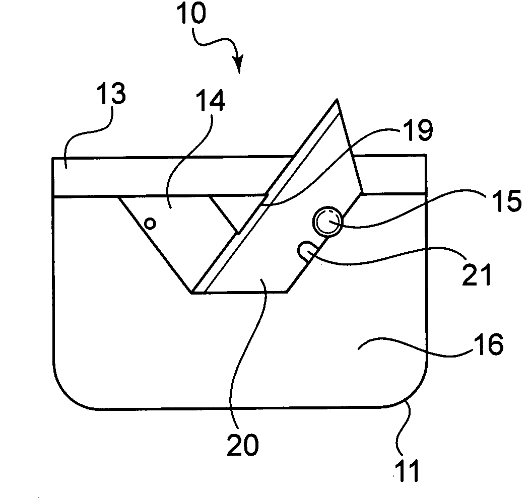
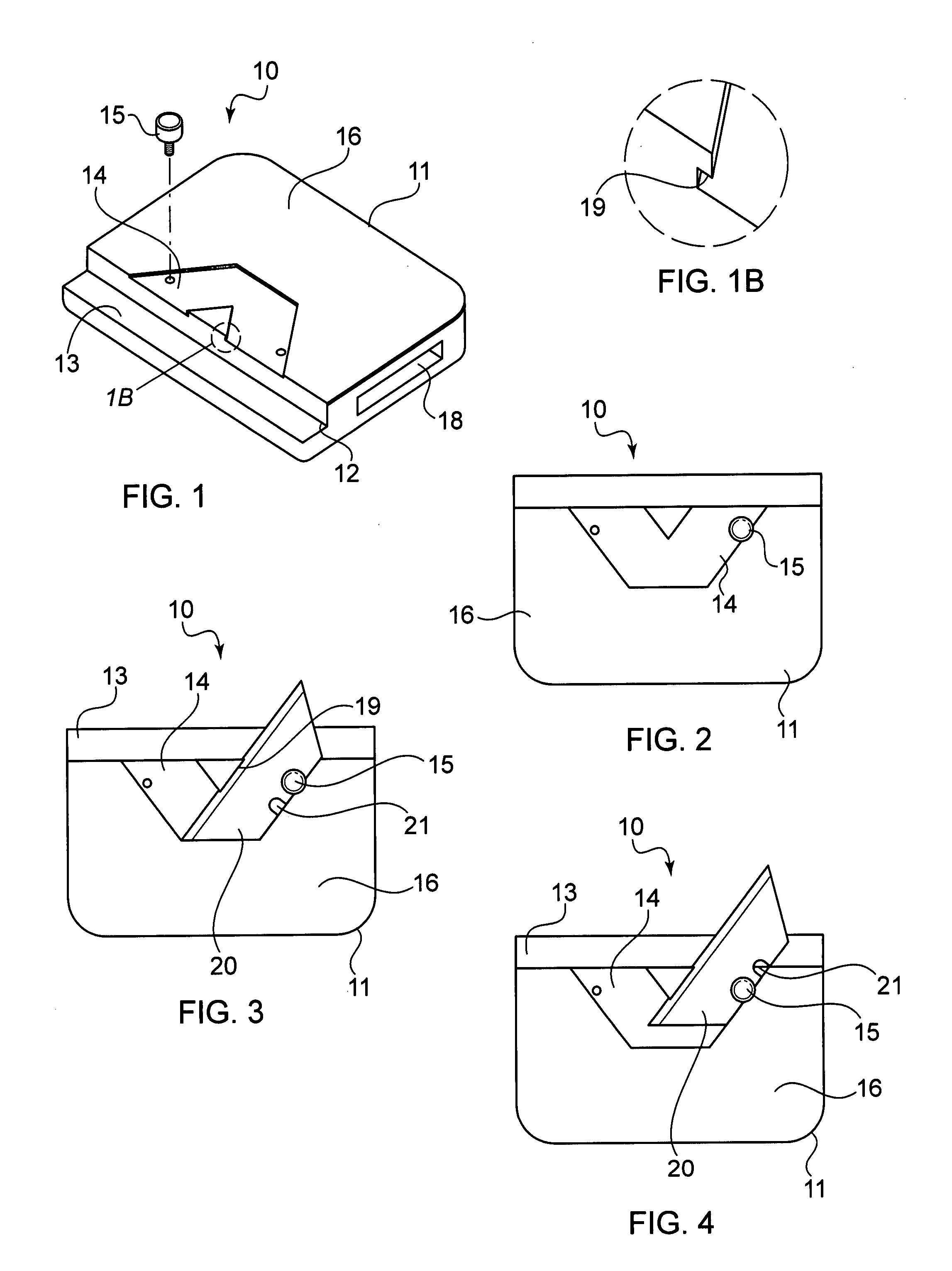
[0025]As shown in FIGS. 1-4, the cutting tool according to the invention comprises a holder a holder body 10 having a handle end 11, and a cutting guide comprising a rabbet 12 disposed opposite handle end 11. Extending from rabbet 12 is an extending rear face 13. There is a blade holding device in the form of a V-shaped notch 14 disposed on front face 16 of holder body 10.

[0026]A blade 20, as shown in FIG. 3 is mounted to holder body 10, by placing a notch 21 of blade 20 adjacent screw 15 and tightening screw 15. Blade 20 then rests securely in V-shaped notch 14. Notch 14 is configured to mount a blade to the holder body such that the blade projects a predetermined distance beyond the front face 16 and extends parallel with extending rear face 13. An alternative blade, such as a small hobby blade, could also be used with the holder body 10 according to the invention. Notch 14 has an overhanging lip 19, which extends over blade 20 and prevents blade 20 from slipping out of notch 14.

[...


PUM


Abstract

A cutting device comprises a holder body having a handle and a rabbet edge guide. The rabbet edge guide is disposed along one edge of the handle body and comprises a rabbet with an extending rear face. Adjacent the rabbet on the front face of the holder body is a blade holder mechanism comprising a V-shaped indentation in the holder body and a securing mechanism for a blade. In use, a blade is secured to the blade holder mechanism so that a cutting edge of the blade extends beyond the holder body and into the rabbet, parallel to the extending rear face. A rabbet cut is made in a ceiling tile by pressing the rear face of the holder body against the edge of the tile to be cut, and running the blade along the tile, to create a straight cut that penetrates only a portion of the depth of the tile. The tile is then rotated 90 degrees, and another cut is made into the edge of the tile, with the rear face of the holder body resting against one of the faces of the tile. The two cuts intersect so that a section of the tile is cut away, creating the required recessed edge.

Description

BACKGROUND OF THE INVENTION[0001]1. Field of the Invention[0002]The invention relates to a cutting tool for creating a recessed edge on a ceiling tile. In particular, the invention relates to a tool having an angled blade of a predetermined dimension, that can be used to accurately finish the edge of a ceiling tile to be placed in a grid in a dropped ceiling.[0003]2. The Prior Art[0004]Ceiling tiles traditionally are sold in pre-set shapes and sizes. They are mounted in a grid that is hung suspended from the ceiling. In some of these arrangements, the ceiling tiles are flat and are shaped to be slightly larger than the openings in the grid. The tiles simply rest on top of the grid and are visible through the openings. In other situations the tiles have recessed edges that rest against the top surface of the grid. The center portion of the tile can then extend below the level of the grid and create a finished appearance. To mount the tiles along the edges of the room, the tile must o...

Claims


Application Information

Patent Timeline
IPC IPC(8): B26B29/00
CPCB26B5/00
Inventor KENTROTAS, ANDREAS
Owner KENTROTAS ANDREAS
Why Eureka
Try Eureka