In-line roller skate frame

a frame and roller skate technology, applied in the field can solve the problems of reducing reducing the service life so as to improve the speed and responsiveness of in-line roller skates, increase the lateral thickness, and increase the rigidity of the fram

Inactive Publication Date: 2002-02-14
V FORMATION
View PDF0 Cites 2 Cited by
  • Summary
  • Abstract
  • Description
  • Claims
  • Application Information

AI Technical Summary

Benefits of technology

0011] In the preferred embodiment of the present invention, depending from the lower surface of both the toe plate and heel plate are first and second laterally spaced-apart, downwardly-extending flanges. In this embodiment, the wheel frame is formed by releasably attaching the first sidewall to the outer lateral faces of the respective first toe and heel plate flanges, and by similarly releasably attaching the second sidewall to the outer lateral faces of the respective second toe and heel plate flanges. This configuration provides increased lateral thickness along the portion of the frame adjacent to the sole of the boot, which results in increased frame rigidity. This additional rigidity at the sole-frame junction can improve the speed and responsiveness of the in-line roller skate.
0012] The present invention allows users to replace one or both sidewalls without replacing the other components of the wheel frame. As a result, the user can inexpensively replace damaged sidewalls, easily reconfigure the skate to carry wheels of a different diameter, and use sidewalls with anodic coatings of different colors. Additionally, as the sidewalls in the present invention are devoid of lateral projections, they can be manufactured by simple machining operations (rather than by casting), and further can be formed of titanium or other lightweight, high-durability materials that are difficult to machine.

Problems solved by technology

Many in-line roller skating activities subject the wheel frames to significant, and potentially damaging, stress levels.
For example, when in-line roller skates are used by roller hockey players, conventional lightweight frames can be bent or fractured when struck by a hockey stick, the hockey puck, or another skate.
The sidewall components of the frame that form the wheel cavity and receive the wheel axles are particularly susceptible to such damage.
If a sidewall on a conventional in-line roller skate having a one-piece wheel frame is damaged, the sidewall alone cannot be replaced; instead, the entire frame must be replaced.
This is a significant drawback, because presently available frames are typically quite expensive due to both the costs associated with casting or machining the single-piece frame and the high price of the lightweight materials used to construct these frames.
In addition, skaters who use their skates for several different activities also face frame replacement difficulties, as a separate frame is often required to accommodate the different sized wheels that provide optimum performance for each different activity.
The inclusion of such lateral projections necessitates either machining or separately casting each sidewall in the manufacturing process, and thus the cost of manufacturing an individual sidewall can be quite high.
An additional disadvantage of these multi-piece frame configurations is that their sidewalls are configured for a specific side of the skate; thus it is necessary to have both a left and right spare sidewall available.
Several additional difficulties with presently available in-line roller skate frames relate to the impact that performance-enhancing design modifications have had on the skate's durability and manufacturing cost.
However, modifying the frame to decrease weight generally decreases the strength and durability of the frame, increases the cost of producing it, or both.
However, forming sidewalls that include such cross members requires machining or casting in the manufacturing process, which can significantly increase the cost of manufacturing the sidewall.

Method used


Image

  • In-line roller skate frame
  • In-line roller skate frame
  • In-line roller skate frame

Examples


Embodiment Construction

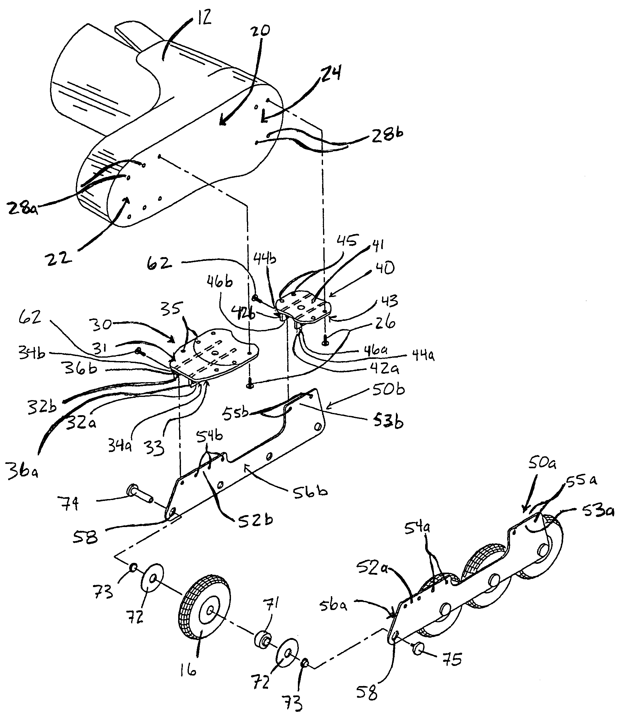
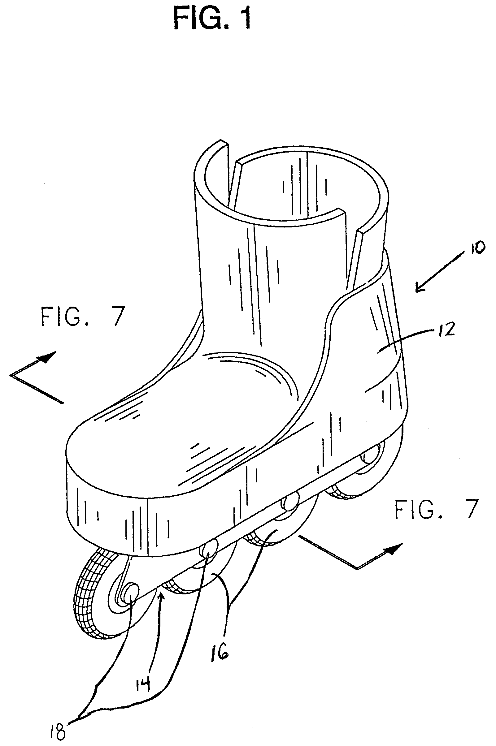
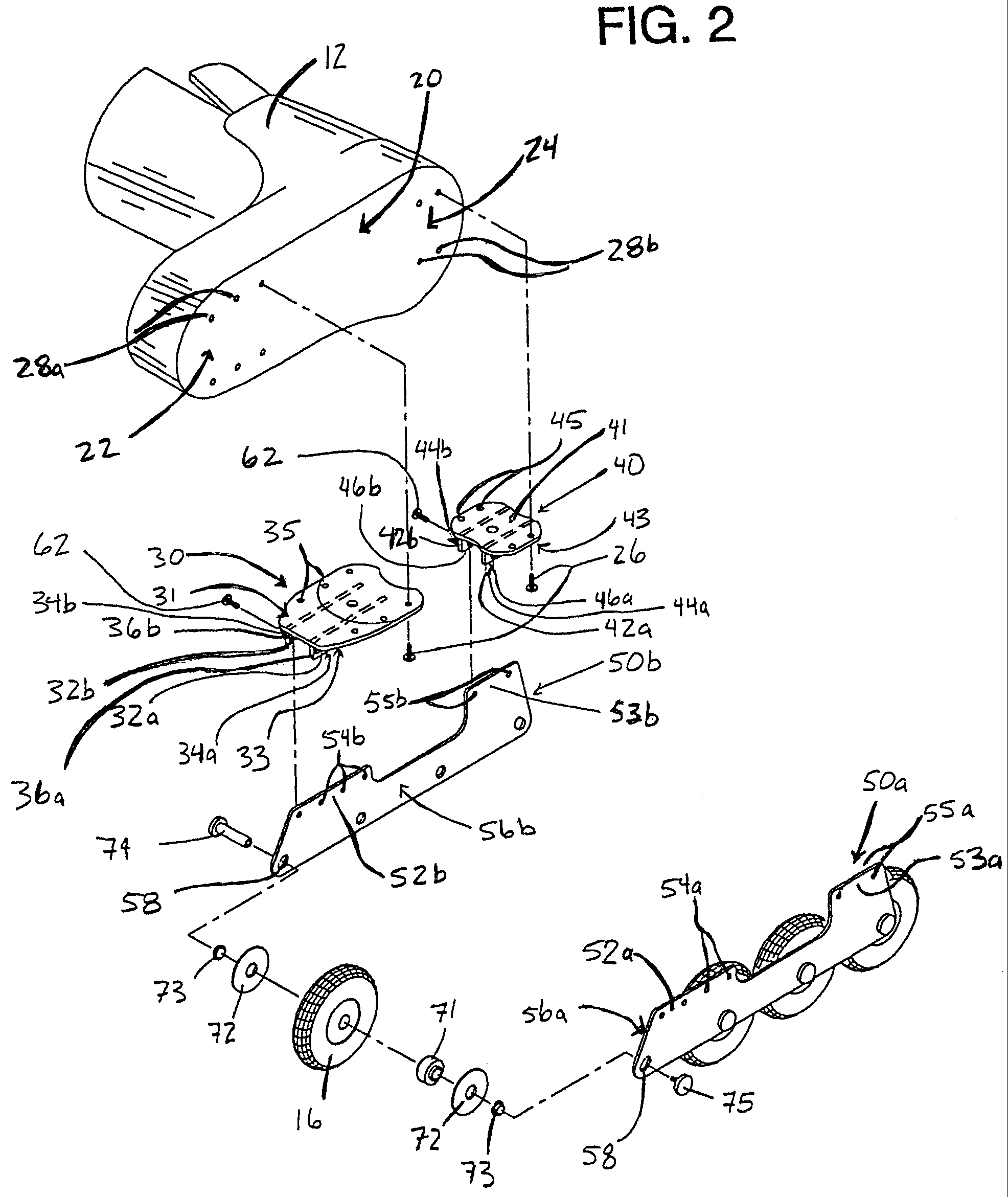
[0020] The present invention will now be described more fully hereinafter with reference to the accompanying drawings, in which preferred embodiments of the invention are shown. This invention may, however, be embodied in many different forms and should not be construed as limited to the embodiments set forth herein. Rather, these embodiments are provided so that this disclosure will be thorough and complete, and will fully convey the scope of the invention to those skilled in the art.

[0021] The present invention relates to an in-line skate frame and associated method for replacing an in-line skate frame. In the description of the present invention that follows, certain terms are employed to refer to the positional relationship of certain structures relative to other structures. As used herein, the term longitudinal and derivatives thereof refer to the general direction defined by the longitudinal axis of the boot or other footwear of the in-line skate that extends between the toe a...


PUM

PropertyMeasurementUnit
coloraaaaaaaaaa
diameteraaaaaaaaaa
thicknessaaaaaaaaaa

Abstract

<heading lvl="0">Abstract of Disclosure</heading> An in-line roller skate has a wheel frame that includes replaceable sidewalls. The in-line roller skate includes a boot having a sole surface with toe and heel portions, a wheel frame, and a plurality of wheels rotatably mounted within the wheel frame. The wheel frame includes a toe plate which is affixed to the toe portion of the sole surface, a heel plate which is affixed to the heel portion of the sole surface, and first and second spaced-apart, downwardly extending sidewalls that are devoid of transverse projections. The frame is formed by releasably attaching the first and second sidewalls to the respective lateral faces of the toe and heel plates.

Description

Cross Reference to Related Applications[0001] This application is a continuation of 09 / 253,633, 1999-02-19, US, now abandoned, which is a continuation of 08 / 946,256, 1997-10-07, now patent 5,873,584, 1999-02-23, which is a continuation of 08 / 373,660, 1995-01-17, now abandoned.Background of Invention[0002] An in-line roller skate typically comprises a boot, a frame attached to the boot, and a plurality of wheels in serial longitudinal alignment attached to the frame via transversely-disposed axles. The frame typically includes a toe plate, a heel plate, and a pair of laterally spaced-apart, downwardly-extending sidewalls. The skate wheels reside in the cavity formed between the sidewalls and below the toe plate and heel plate. Most commonly, the frame is formed by casting or machining as a single integral component.[0003] In-line skates are used in a variety of activities, including roller hockey, racing, and recreational skating. As the number and variety of activities for in-line s...

Claims


Application Information

Patent Timeline
Patent Type & Authority Applications(United States)
IPC IPC(8): A63C17/00A63C17/06
CPCA63C17/068Y10T29/49716A63C2203/42
Inventor WRIKE , MICHAEL C.
Owner V FORMATION
Why Eureka
Try Eureka