System and method for cooling electronic equipment

a technology of electronic equipment and cooling system, which is applied in the direction of cooling/ventilation/heating modification, domestic cooling apparatus, climate sustainability, etc., can solve the problems of wasting a great deal of energy by producing cooling air that isn't utilized effectively, not meeting all the requirements of a modern data center cooling system, and the mix of warm and cool air is much less effective at cooling the components

Active Publication Date: 2009-03-05
VERTIV CORP
View PDF82 Cites 22 Cited by
  • Summary
  • Abstract
  • Description
  • Claims
  • Application Information

AI Technical Summary

Benefits of technology

[0006]A cooling system and method in accordance with the principles of the present invention includes a fan cartridge configured for mounting within a return air path that returns warmed air to a data center's air conditioner. Such a fan cartridge may be mounted within a chassis that is affixed to the structure providing the return air path. Each fan cartridge includes a fan, a fan controller, and a display configured to be viewed by a user positioned on the floor proximate the electronics cabinet for which the fan cartridge is providing air movement. The fan controller is configured to permit such a fan cartridge to operate independently, with all control functions, power, and communications positioned within the return air path.
[0007]In accordance with the principles of the present invention, a plurality of fan cartridges may be mounted in a single chassis, thereby providing redundant air movement for a given duct/cabinet combination. In an illustrative embodiment, each of the redundant fan cartridges is configured to communicate with the other and to thereby regulate its operational speed to meet that of the

Problems solved by technology

This mixture of warm and cool air is much less effective at cooling the components.
In this way, a great deal of the energy is wasted by producing cooling air that isn't utilized effectively.
Although such a configuration provides improved efficiency compared to mo

Method used


Image

  • System and method for cooling electronic equipment
  • System and method for cooling electronic equipment
  • System and method for cooling electronic equipment

Examples


Embodiment Construction

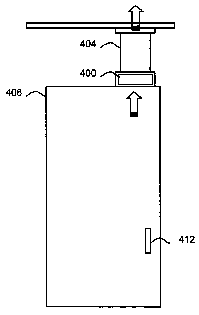
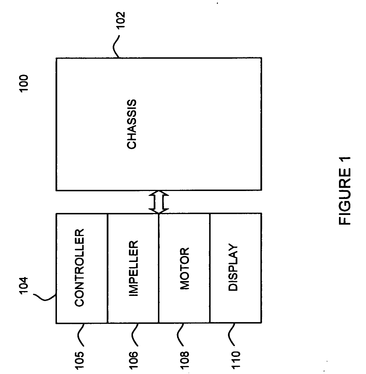
[0015]In the conceptual block diagram of FIG. 1 a return air path fan 100 in accordance with the principles of the present invention includes a chassis 102 configured for mounting within a cooling system, such as a warm air return path that may be employed within a data center cooling system. The chassis 102 provides support for a fan cartridge 104. The chassis 102 and fan cartridge 104 may be configured for convenient insertion in and withdrawal from such a return air path. The cartridge 104 may be guided and supported, for example, by guide rails that direct the cartridge 104 to a fully engaged position within the duct. The guide rails may, for example, be included in a chassis such as discussed in greater detail in the discussion related to FIG. 5. In the fully engaged position, a mechanism with the fan cartridge 104 may, for example, be engaged with a mating mechanism within the chassis to provide power to the fan cartridge 104. Mating “male” and “female” plug ends or card edge ...


PUM


Abstract

A cooling system and method in accordance with the principles of the present invention employs a fan cartridge that includes a fan and a fan controller and is configured for mounting within an electronics cabinet's warm air return path in a data center cooling system. The fan cartridge may also include a display panel which may be used to convey operational information relative to the fan cartridge. A plurality of such fan cartridges may be mounted within the electronic cabinet's warm air return path to provide redundant air flow supply for the associated electronics cabinet.

Description

RELATED APPLICATIONS[0001]Not applicableFIELD OF THE INVENTION[0002]The invention relates to electronic cooling systems and more particularly to systems and methods for cooling an enclosed rack of electronic equipment such as may be found in a server farm, for example.BACKGROUND OF THE INVENTION[0003]Large information handling system installations, such as data centers, server farms, and telecommunications switching systems (all referred to hereinafter generically as “data centers”) generate a great deal of waste heat that must be dissipated in order for the systems to continue operation. The capacity of such data centers continues to grow at a rapid pace to meet the demands of an increasingly “wired” society. Not only are such installations steadily increasing in computing capacity and overall volume, their power density is also increasing. Greater size and density, naturally, leads to greater or improved cooling requirements.[0004]Conventional data center cooling systems typically...

Claims


Application Information

Patent Timeline
IPC IPC(8): F25D23/12
CPCH05K7/20836H05K7/20745Y02D10/00H05K7/2059
Inventor GERMAGIAN, MARK
Owner VERTIV CORP
Why Eureka
Try Eureka