Air conditioning system for communication equipment and controlling method thereof

Inactive Publication Date: 2009-03-05
SOLID VENTUS INC
View PDF2 Cites 2 Cited by
  • Summary
  • Abstract
  • Description
  • Claims
  • Application Information

AI Technical Summary

Benefits of technology

[0021]Thanks to the above features, the air conditioning system for communication equipment and the control method thereof according to the present invention, constructed as mentioned above, provide advantages in that the sizes of indoor and outdoor modules are decreased, noise generation is reduced, and n

Problems solved by technology

The communication equipment is likely to have loose connections or to break down due to frequent heat generation, whereby the possibility of malfunction increases.
However, in the conventional air condit

Method used


Image

  • Air conditioning system for communication equipment and controlling method thereof
  • Air conditioning system for communication equipment and controlling method thereof
  • Air conditioning system for communication equipment and controlling method thereof

Examples


Example

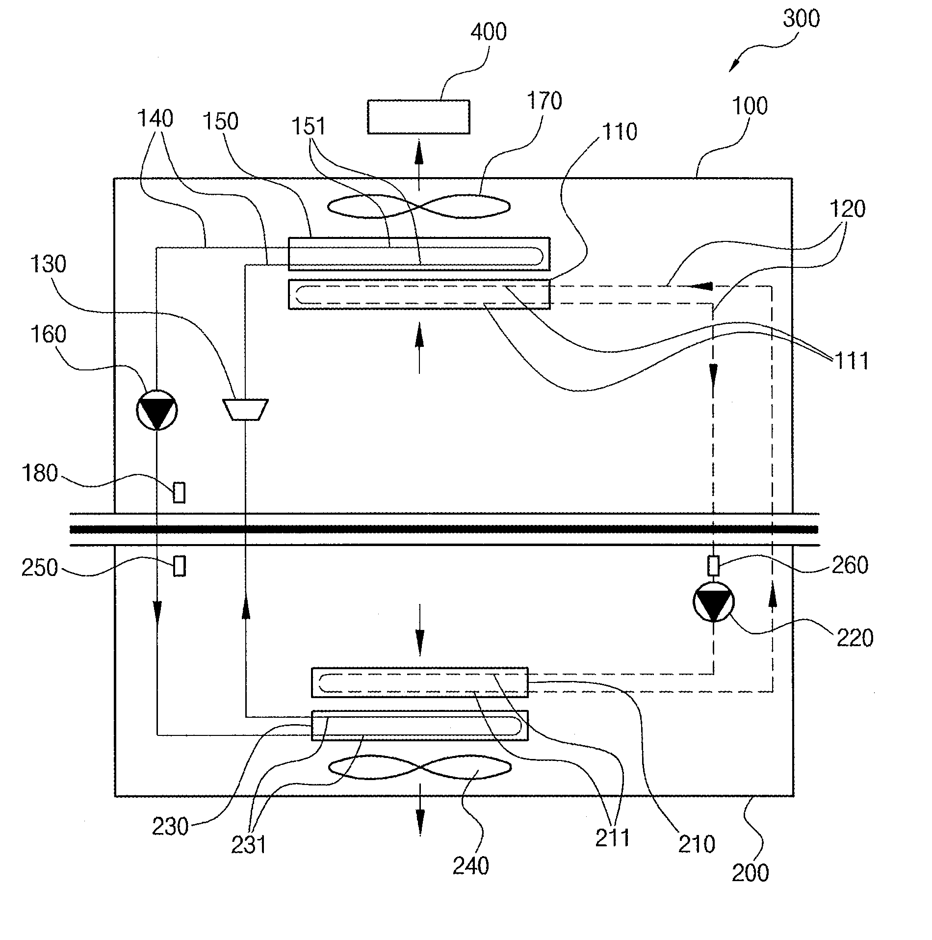
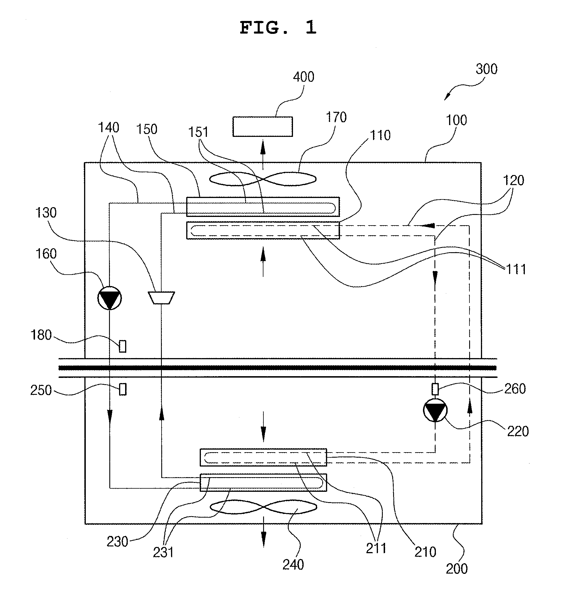
DESCRIPTION OF REFERENCE NUMERALS FOR MAIN PARTS OF DRAWINGS

[0031]100, 100′: indoor modules[0032]110, 110′: first indoor heat exchangers[0033]111, 111′: heat exchange tubes[0034]120, 120′: brine pipes[0035]130, 130′: expansion valves[0036]140, 140′: refrigerant pipes[0037]150, 150′: second indoor heat exchangers[0038]151, 151′: heat exchange tubes[0039]160, 160′: compressors[0040]170, 170′: indoor blowers[0041]180, 180′: indoor temperature sensors[0042]200, 200′: outdoor modules[0043]210, 210′: first outdoor heat exchangers[0044]211, 211′: heat exchange tubes[0045]220, 220′: brine pumps[0046]230, 230′: second outdoor heat exchangers[0047]231, 231′: heat exchange tubes[0048]240: outdoor blower[0049]240′: third outdoor heat exchanger[0050]241′: heat exchange tube[0051]250: outdoor temperature sensor[0052]250′: fourth outdoor heat exchanger[0053]251′: heat exchange tube[0054]260: brine temperature sensor[0055]260′: outdoor blower[0056]270′: outdoor temperature sensor[0057]280′: brine t...


PUM


Abstract

An air conditioning system for communication equipment includes an indoor module placed inside a base station and an outdoor module placed outside the base station. The indoor module has a first indoor heat exchanger installed on a brine pipe and having a heat exchange tube, an expansion valve installed on a refrigerant pipe, a second indoor heat exchanger having a heat exchange tube to which the refrigerant pipe is connected, a compressor for compressing refrigerant, and an indoor blower. The outdoor module has a brine pump installed on the brine pipe, a first outdoor heat exchanger having a heat exchange tube to which the brine pipe extending from the brine pump and the first indoor heat exchanger is connected, a second outdoor heat exchanger having a heat exchange tube to which the refrigerant pipe, extending from the compressor and the expansion valve, is connected, and an outdoor blower.

Description

TECHNICAL FIELD[0001]The present invention relates to air conditioning of communication equipment, and more particularly, to an air conditioning system for communication equipment which is arranged in a base station, a booth, etc. to cool communication equipment disposed therein, and is decreased in size to prevent noise generation, overheating and malfunction thereof and to ensure stable operation of the communication equipment, and a control method thereof.BACKGROUND ART[0002]A conventional air conditioning system employs evaporation heat which is absorbed by refrigerant from the surroundings when the refrigerant evaporates. As the refrigerant, liquids such as ammonia, Freon, an azeotropic refrigerant mixture, chloromethyl, and so on, which can easily evaporate even at low temperatures, are generally used.[0003]In the conventional air conditioning system, as a vaporized refrigerant, which is compressed by a compressor to a high pressure, flows through a condenser, the refrigerant ...

Claims


Application Information

Patent Timeline
Owner SOLID VENTUS INC
Why Eureka
Try Eureka