Heat exchanger

Inactive Publication Date: 2009-03-05
BEHR GMBH & CO KG
View PDF21 Cites 33 Cited by
  • Summary
  • Abstract
  • Description
  • Claims
  • Application Information

AI Technical Summary

Benefits of technology

[0009]The invention addresses this; it is an object of the invention to specify a heat exchanger in which the base is of improved design. In particular, it is intended that a base is comparatively simple to produce. It is also intended that the tank cover of a tank is connected to the base in a particularly adva

Problems solved by technology

This fundamentally leads to comparatively uneconomical production.
Furthermore, the often-occurring potential risk in the case of single-piece bases of premature damage to the material, or of production-induced undesired material thinn

Method used


Image

  • Heat exchanger
  • Heat exchanger
  • Heat exchanger

Examples


Embodiment Construction

[0071]Below, the same reference symbols are used for identical or functionally equivalent parts.

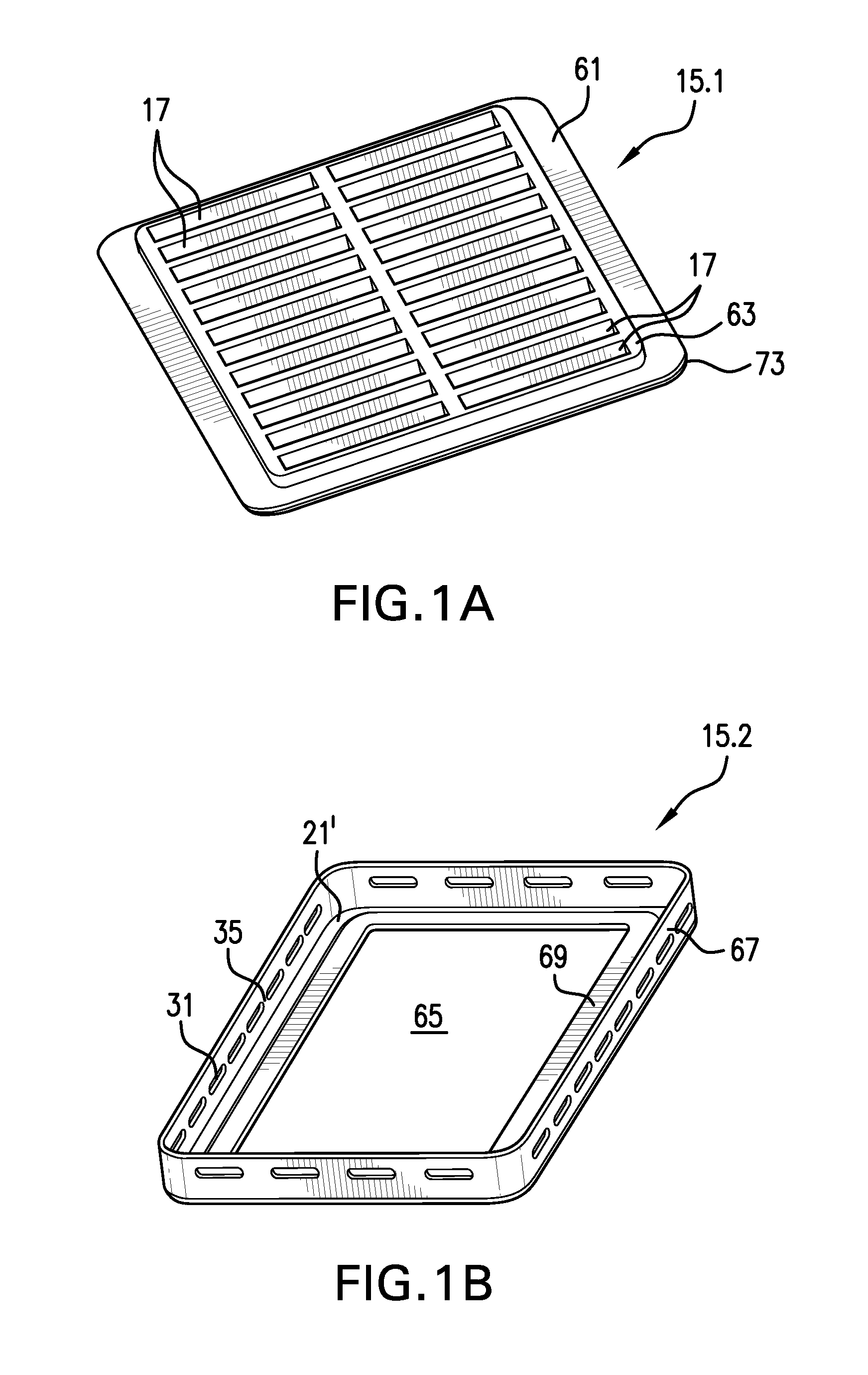
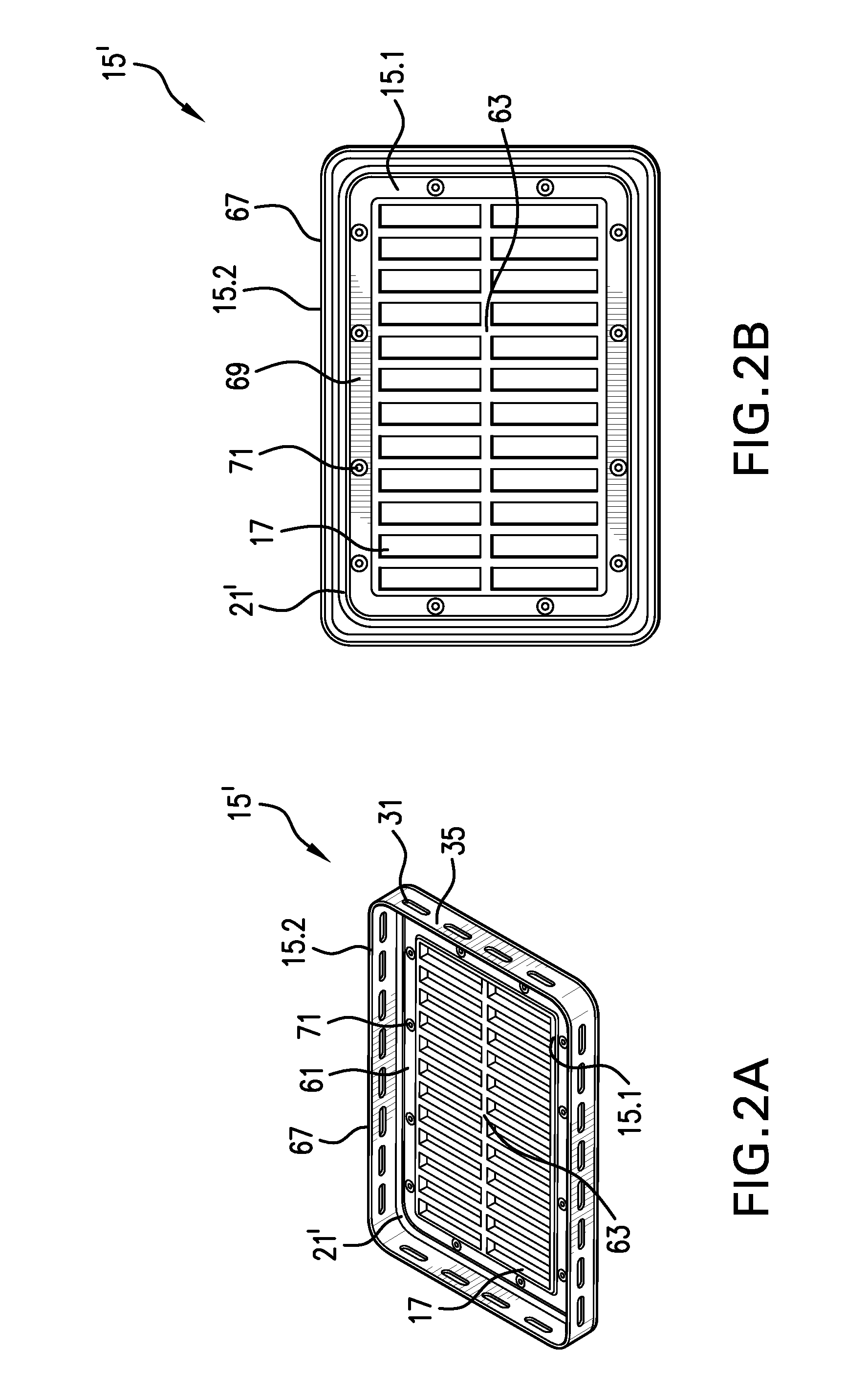
[0072]FIG. 1 shows, in view A, a first base part 15.1 which is formed as an inner base part in the form of a base plate with a plurality of passage openings 17 for flow ducts 5. Here, the passage openings 17 are in the present case arranged in two rows and are formed by a podium which is elevated above a base plate edge region 61, specifically as a relatively thick inner base region 63 which is formed within the base plate edge region 61. Here, a passage opening 17 is of substantially rectangular design in order to be able to hold a flow duct 5 in the form of a flat tube.

[0073]The second base part 15.2 shown in view B in FIG. 1 is formed as an outer base part in the form of a single base frame part, and in the present case, has an L-shaped cross section. The free area 65 of the base frame part corresponds substantially to the area of the podium 63, and can thus hold the passage openings 1...


PUM

PropertyMeasurementUnit
Lengthaaaaaaaaaa
Lengthaaaaaaaaaa
Thicknessaaaaaaaaaa

Abstract

Specified is a heat exchanger for an exchange of heat between a first fluid, in particular charge air or an exhaust gas, and a second fluid, in particular a coolant, having a block for the separate and heat-exchanging guidance of the first and second fluids, which block has a number of flow ducts which can be traversed by the first fluid and a housing which holds the flow ducts and which can be traversed by the second fluid, at least one casing cover which is flow-connected to the flow ducts, a base which is fixed to the casing cover and which is provided with one or with a plurality of passage openings for the flow ducts, wherein the base is composed of at least one first base part and a second base part.

Description

CROSS-REFERENCE TO RELATED PATENT APPLICATIONS[0001]The right of foreign priority is claimed under 35 U.S.C. § 119(a) based on Federal Republic of Germany Application No. 10 2007 040 793.0, filed Aug. 28, 2007, the entire contents of which, including the specification, drawings, claims and abstract, are incorporated herein by reference.BACKGROUND OF THE INVENTION[0002]The invention relates to a heat exchanger for an exchange of heat between a first fluid and a second fluid, having: a block for the separate and heat-exchanging guidance of the first and second fluids, which block has a number of flow ducts which can be traversed by the first fluid and a housing which holds the flow ducts and which can be traversed by the second fluid; at least one casing cover which is flow-connected to the flow ducts, a base which is fixed to the casing cover and which is provided with one or with a plurality of passage openings for flow ducts. The invention also relates to a use of the heat exchange...

Claims


Application Information

Patent Timeline
IPC IPC(8): F28F9/02
CPCF02M25/0737F28F9/02F28F9/0219Y02T10/121F28F21/067F28F21/08F28F21/04F28F2009/029F02M26/32Y02T10/12F28F9/0131
Inventor HEMMINGER, ROLANDSCHIENEMANN, MARKREIER, WOLFGANG
Owner BEHR GMBH & CO KG
Why Eureka
Try Eureka