Flyback LED drive circuit with constant current regulation

a technology of driving circuit and constant current, which is applied in the direction of electric variable regulation, process and machine control, instruments, etc., can solve the problems of high ripple current at led, the drive circuit cannot fit for a wide input voltage range,

Inactive Publication Date: 2009-03-05
FAIRCHILD TAIWAN
View PDF2 Cites 41 Cited by
  • Summary
  • Abstract
  • Description
  • Claims
  • Application Information

AI Technical Summary

Benefits of technology

[0005]A LED drive circuit for the LEDs is provided. It includes an inductive device coupled to an input voltage. A power transistor is connected to the inductive device in series to control a switching current of the inductive device. A flyback diode is coupled to the inductive device. A plurality of LEDs are connected to the inductive device through the flyback diode. A control circuit is coupled to detect the switching current of the inductive device for generating a switching signal to control the power transistor. The control circuit controls the LED current as a constant through controlling the switching current of the inductive device when the power transistor is turned on. The energy is stored into the inductive device when the power transistor is turned on. The stored energy is delivered to the LEDs via the flyback diode when the power transistor is turned off. A capacitor is connected to the LEDs in parallel to make a filter for the LED current.

Problems solved by technology

However, the drawback of this prior art is the drive circuit does not fit for a wide input voltage range.
Another disadvantage of this prior art is the high ripple current at LED.

Method used


Image

  • Flyback LED drive circuit with constant current regulation
  • Flyback LED drive circuit with constant current regulation
  • Flyback LED drive circuit with constant current regulation

Examples


Embodiment Construction

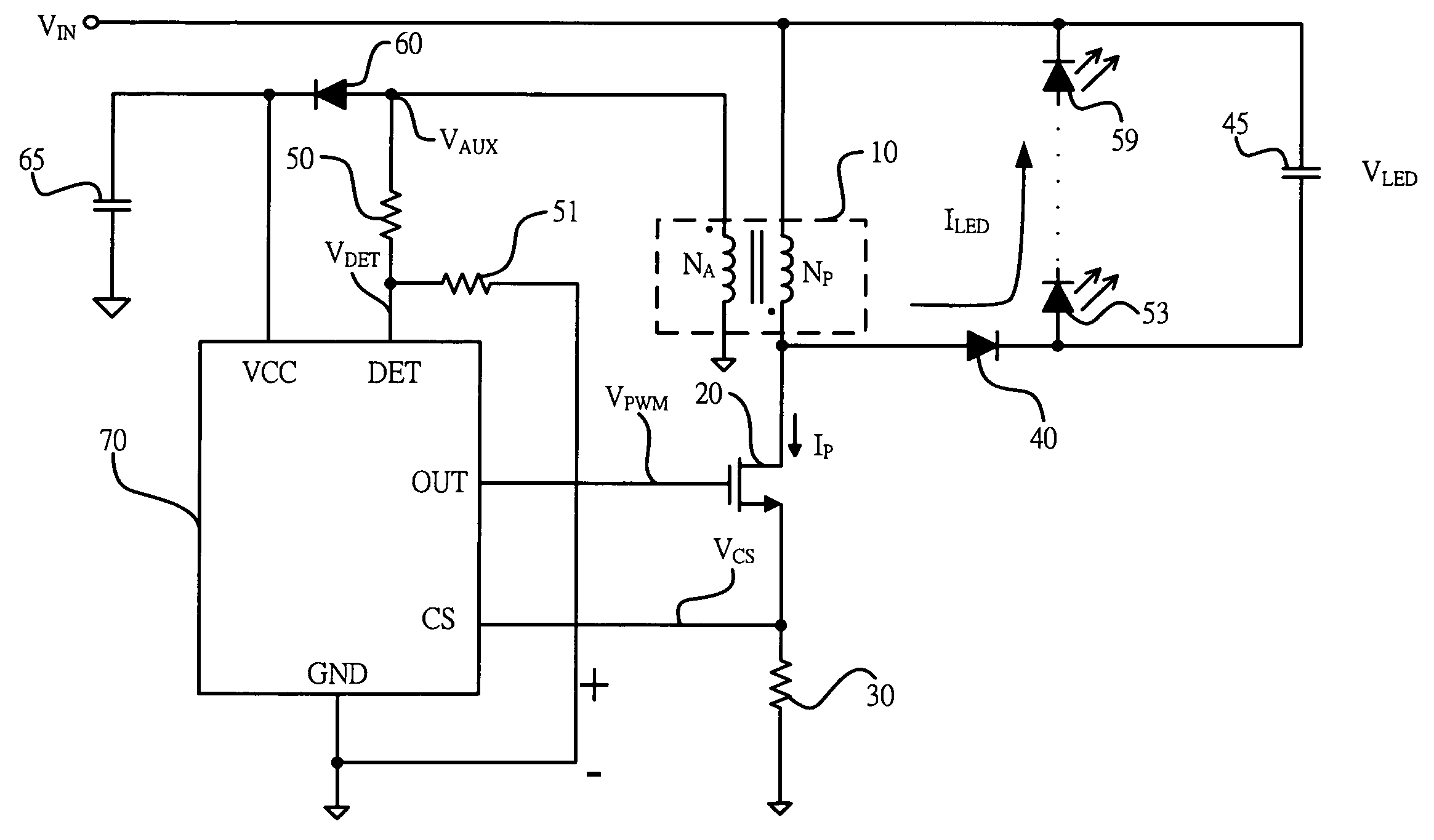
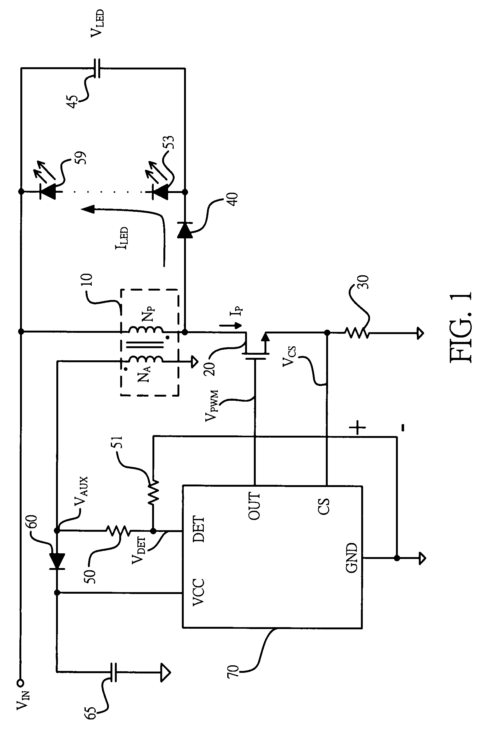
[0017]FIG. 1 shows a circuit diagram of a flyback LED drive circuit. It includes an inductive device 10 having an auxiliary winding NA and a main winding NP. The inductive device 10 serves as an inductor. The main winding NP of the inductive device 10 is coupled to an input voltage VIN. The main winding NP provides an inductance LP for producing a switching current IP. The auxiliary winding NA provides a power source to a control circuit 70. A power transistor 20 is connected to the inductive device 10 in series to control the switching current IP of the inductive device 10. No switching current is flowed from the inductive device 10 to the LEDs 53 . . . 59 when the power transistor 20 is turned on. A flyback diode 40 is connected to the inductive device 10. The control circuit 70 is coupled to detect the switching current IP of the inductive device 10 through a current-sense device, such as a resistor 30, for generating a switching signal VPWM to control the power transistor 20.

[00...


PUM


Abstract

A flyback LED drive circuit for the plurality of LEDs is provided. An inductive device is coupled to an input voltage. A power transistor is connected to the inductive device in series to control the switching current of the inductive device. The energy is stored into the inductive device when the power transistor is turned on. The stored energy is delivered to the plurality of LEDs via a flyback diode when the power transistor is turned off. A control circuit is utilized to detect the switching current of the inductive device for generating a switching signal to provide a constant current to the plurality of LEDs.

Description

BACKGROUND OF THE INVENTION[0001]1. Field of the Invention[0002]The present invention relates to a LED drive circuit, and more specifically relates to a control circuit for LED driver.[0003]2. Description of Related Art[0004]Various switching control circuit have been proposed to drive LED, such as “Switching LED driver” by Yang, U.S. Pat. No. 7,245,089. However, the drawback of this prior art is the drive circuit does not fit for a wide input voltage range. Another disadvantage of this prior art is the high ripple current at LED. The object of the present invention is to solve foregoing problems and achieve a high efficiency LED drive circuit. The size and the cost of the LED drive circuit can be reduced.SUMMARY OF THE INVENTION[0005]A LED drive circuit for the LEDs is provided. It includes an inductive device coupled to an input voltage. A power transistor is connected to the inductive device in series to control a switching current of the inductive device. A flyback diode is coup...

Claims


Application Information

Patent Timeline
Patent Type & Authority Applications(United States)
IPC IPC(8): H05B37/02
CPCY02B20/347H05B33/0818Y02B20/30H05B45/392H05B45/385
Inventor YANG, TA-YUNG
Owner FAIRCHILD TAIWAN
Why Eureka
Try Eureka