
Wireless communication apparatus, and feedback information generating method

a communication apparatus and feedback technology, applied in multiplex communication, diversity/multi-antenna systems, baseband system details, etc., can solve the problem of not being able to use channel information of the opposite channel, and achieve the effect of accurately reproducing channel information and not increasing the amount of feedback information

Inactive Publication Date: 2009-03-05
PANASONIC CORP
View PDF3 Cites 19 Cited by
  • Summary
  • Abstract
  • Description
  • Claims
  • Application Information

AI Technical Summary

Benefits of technology

[0014]The present invention makes it possible to accurately reproduce channel information on the transmitting side without increasing the amount of feedback information.

Problems solved by technology

On the other hand, with FDD, frequency bands are different in uplink and downlink, and the reciprocity of the channel is not formed in uplink and downlink, and, therefore, it is not possible to use channel information of the opposite channel.

Method used


Image

  • Wireless communication apparatus, and feedback information generating method
  • Wireless communication apparatus, and feedback information generating method
  • Wireless communication apparatus, and feedback information generating method

Examples


embodiment 1

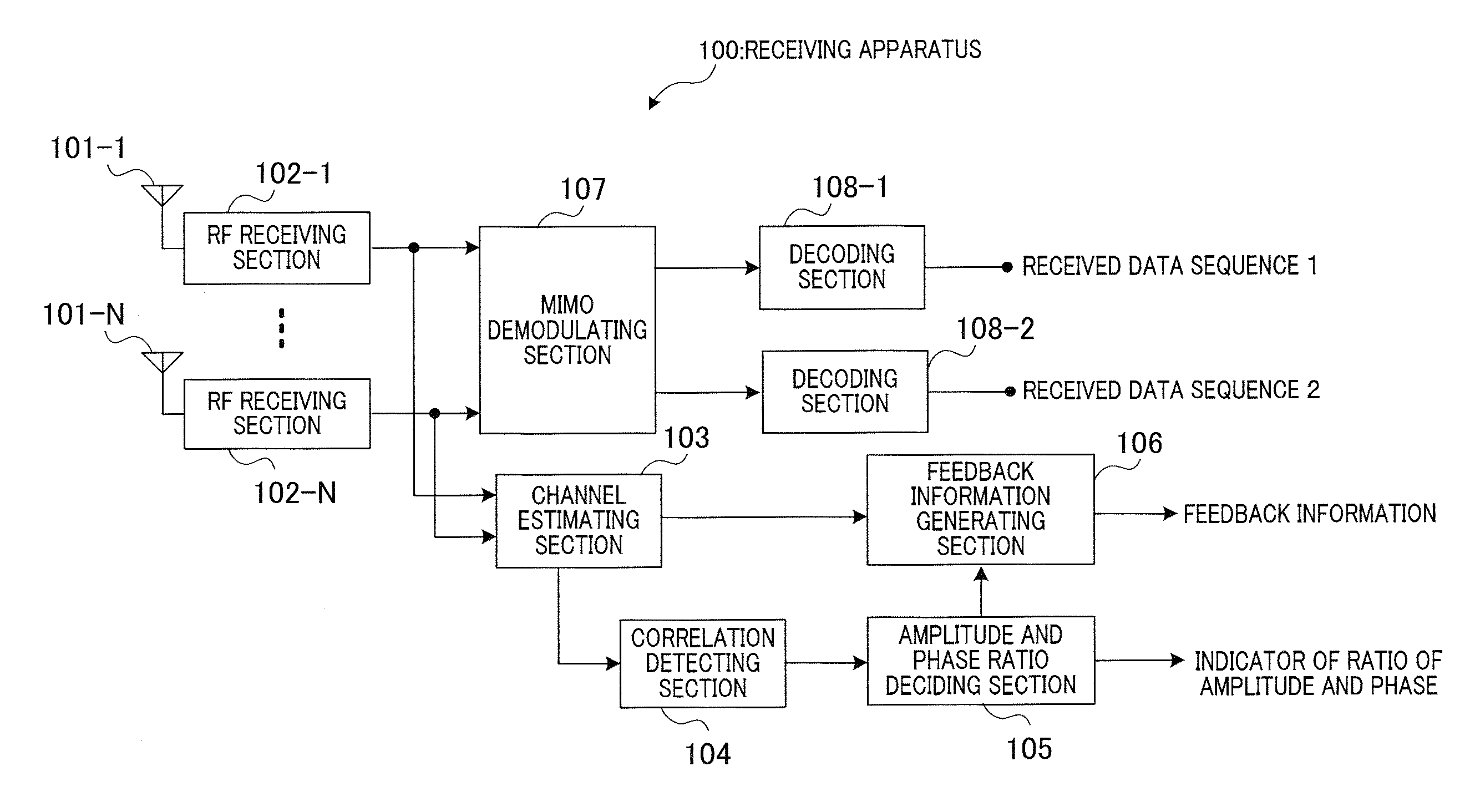
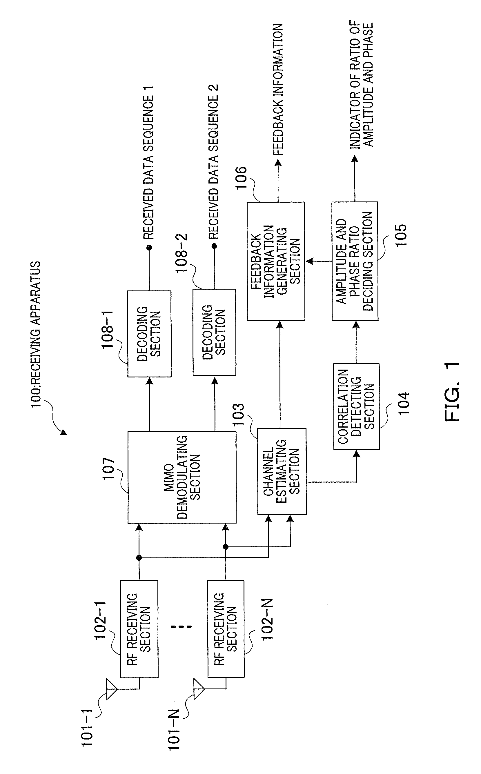
[0029]FIG. 1 is a block diagram showing a configuration of receiving apparatus 100 according to Embodiment 1 of the present invention. In this figure, RF receiving sections 102-1 to 102-N convert carrier signals in a radio frequency band received through antennas 101-1 to 101-N from a transmitting apparatus into baseband signals, and outputs converted baseband signals to channel estimating section 103 and MIMO demodulating section 107. Channel estimating section 103 demodulates pilot signals from the baseband signals outputted from RF receiving sections 102-1 to 102-N and carries out channel estimation using the demodulated pilot signals. Here, a “channel” refers to a propagation path for a signal which is transmitted from a transmitting antenna and is received at a receiving antenna. In this channel, the amplitude and the phase of a signal varies due to the influence of multipath fading. “Channel estimation” refers to the measurement of this amplitude and phase variation. Further, ...

embodiment 2

[0056]FIG. 11 is a block diagram showing a configuration of receiving apparatus 400 according to Embodiment 2 of the present invention. FIG. 11 differs from FIG. 1 in changing amplitude and phase ratio deciding section 105 to resolution deciding section 401.

[0057]In FIG. 11, resolution deciding section 401 decides the resolution for quantizing channel information in feedback information generating section 402 based on the correlation value outputted from correlation detecting section 104, outputs the decision result (resolution used in quantization) to feedback information generating section 402 and feeds back an indicator indicating the decision result to the transmitting apparatus.

[0058]Feedback information generating section 402 quantizes channel information outputted from channel estimating section 103 according to the detection result outputted from resolution deciding section 401, and generates feedback information included in the quantized amplitude and phase.

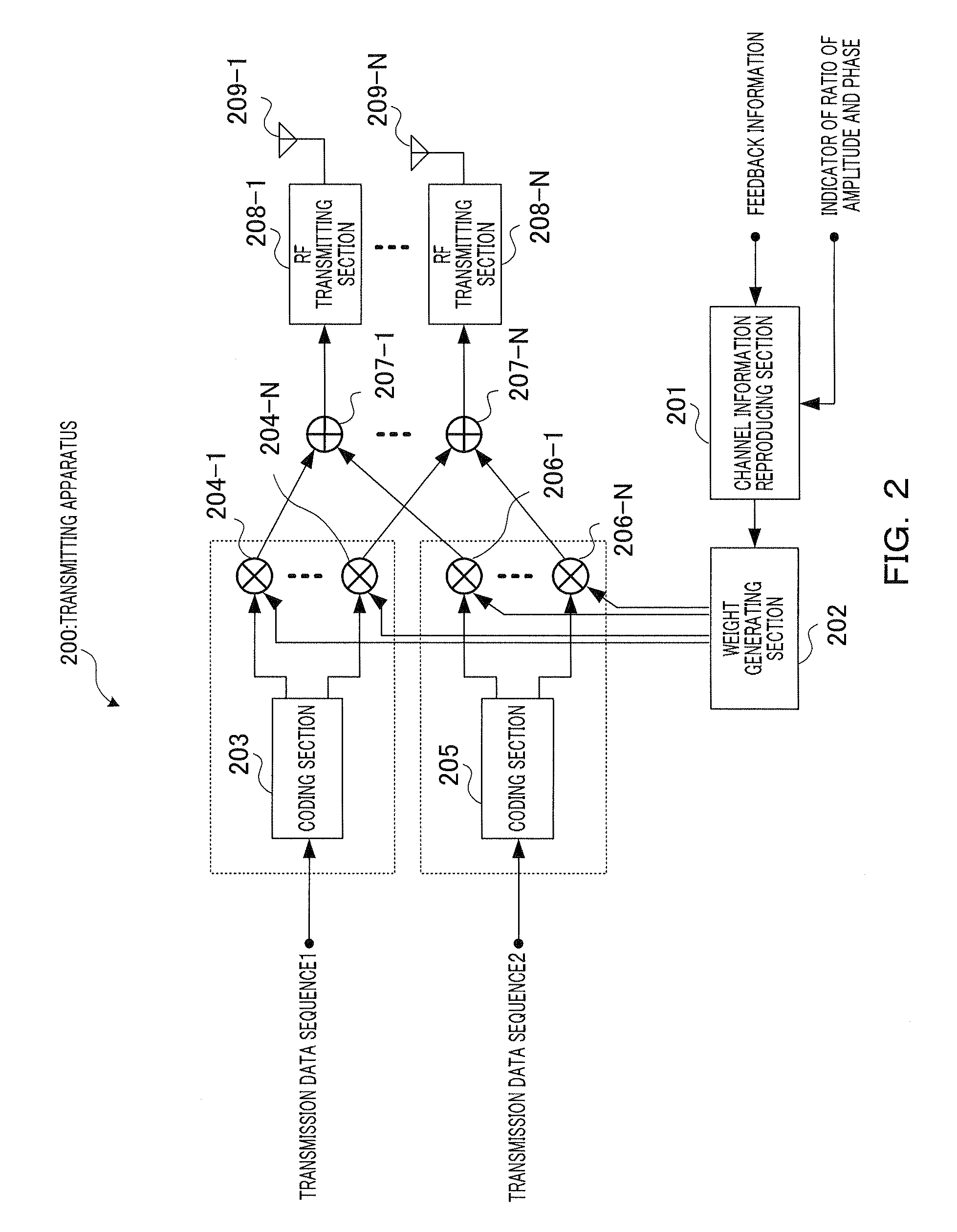
[0059]The transm...


PUM


Abstract

A wireless communication apparatus that allows channel information to be reproduced with high precision at a transmitting end without increasing feedback information amount. In this apparatus, a channel estimating part (103) uses received pilot signals to perform channel estimation for each channel. A correlation detecting part (104) uses the result of the channel estimation to obtain correlation values between the channels, thereby detecting correlation values of all channels. An amplitude / phase ratio determining part (105) determines, based on the correlation values, the quantization bit ratio of the amplitude and phase of channel information to be used when those amplitude and phase are quantized. A feedback information generating part (106) quantizes the channel information in accordance with the determined ratio of the amplitude and phase.

Description

TECHNICAL FIELD[0001]The present invention relates to a wireless communication apparatus and feedback information generation method used in a wireless communication system using a MIMO (Multiple Input Multiple Output) technique which carries out wireless communication by receiving at a plurality of antennas a radio signal transmitted through a plurality of antennas.BACKGROUND ART[0002]In recent years, transmission schemes for realizing high-speed transmission of a great amount of data is studied, and attention is directed to the MIMO transmission technique using a plurality of antennas. MIMO transmission makes it possible to increase transmission throughput by using a plurality of antennas at the same time and at the same frequency, and transmitting signals through a plurality of different channels. This is referred to as “space division multiplexing” (“SDM”).[0003]The SDM schemes include an antenna space SDM for transmitting different signal streams through antennas and a beam spac...

Claims


Application Information

Patent Timeline
IPC IPC(8): H04B7/02H04J99/00
CPCH04B7/0421H04L25/0206H04B7/065H04B7/0626H04L25/0204
Inventor YUDA, YASUAKIIMAI, TOMOHIROHOSHINO, MASAYUKIKIMURA, RYOHEI
Owner PANASONIC CORP
Learn More