

Method for dynamically allocating link width of riser card
a dynamical allocation and riser card technology, applied in the field of logic circuit allocation methods, can solve the problems of increasing the design cost of the riser card, limited space available, inconvenience in handling the riser card, etc., and achieve the effect of optimizing the link width allocation and saving the design cos
- Summary
- Abstract
- Description
- Claims
- Application Information
AI Technical Summary
Benefits of technology
Problems solved by technology
Method used
Image

Examples
first embodiment
The First Embodiment
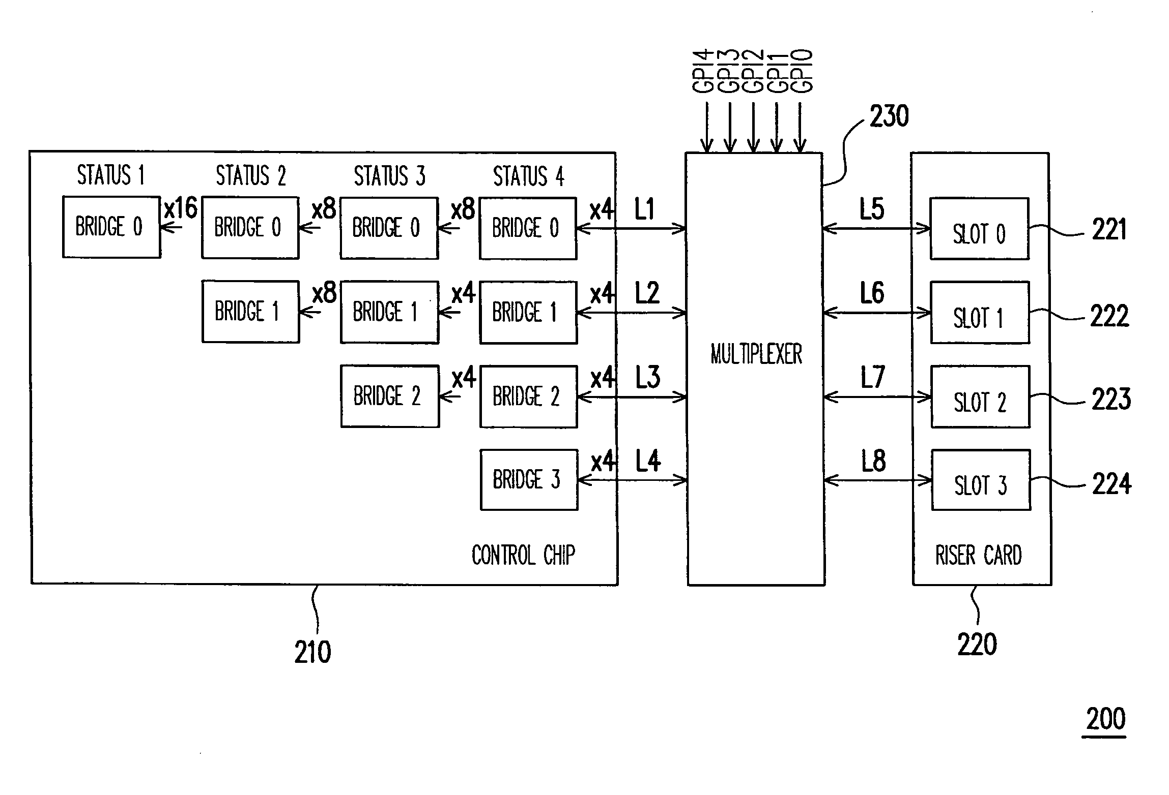
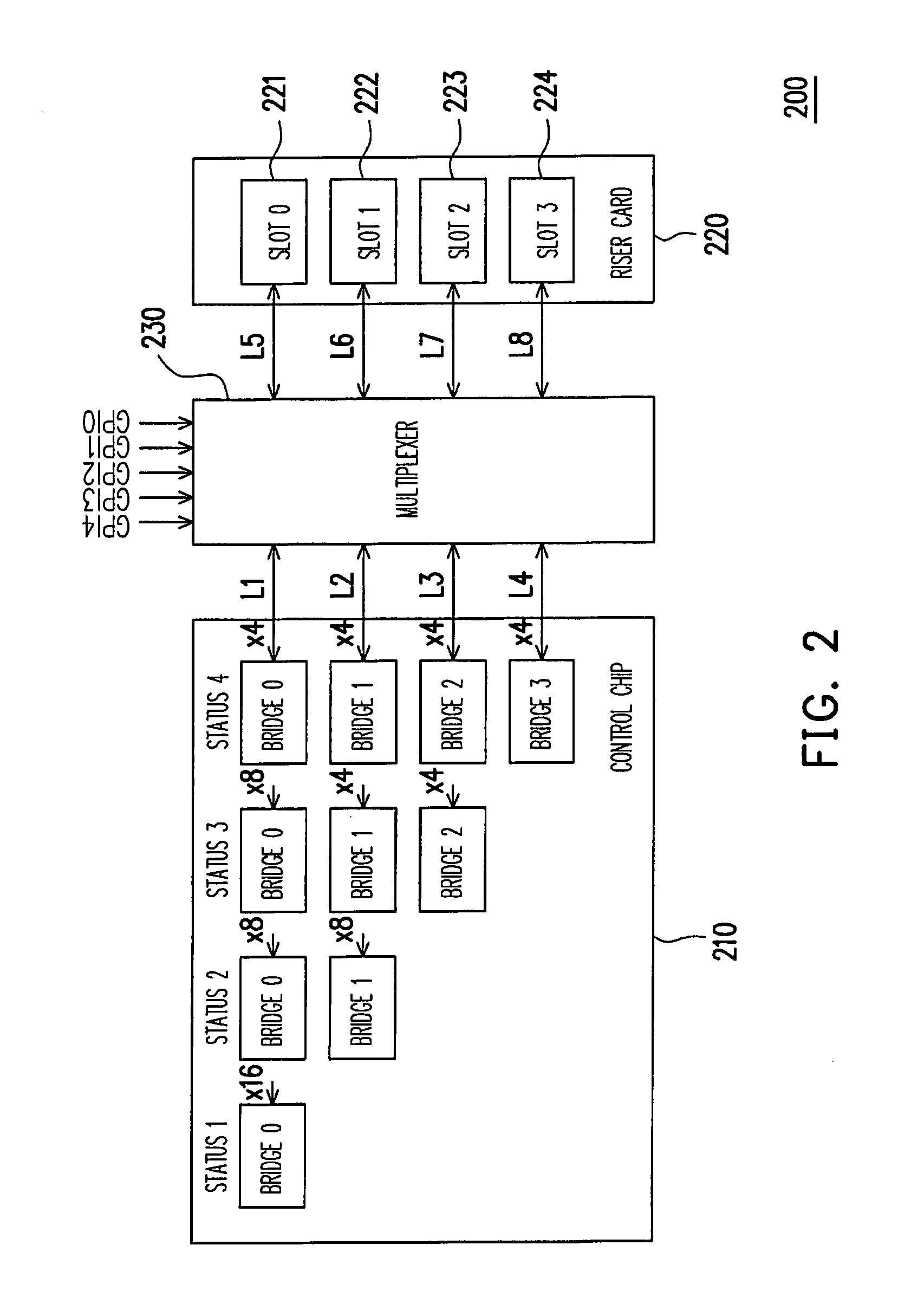
[0032]FIG. 2 is a block diagram of a system adopting the method for dynamically allocating link width of a riser card according to the first embodiment of the present invention. Referring to FIG. 2, a riser card 220 is inserted into a slot (not shown) on the motherboard of a system 200. Four slots are disposed on the riser card 220 (including a slot 0, a slot 1, a slot 2 and a slot 3) for accepting 1-4 cards to be inserted therein, wherein the slots are, for example, PCI-E slots and the cards are, for example, PCI-E cards, but the present invention is not limited to them.
[0033]Once the riser card 220 is installed on the system 200, the system 200 would set the configuration of a control chip 210, meanwhile the setting value corresponding to the configuration is written in a retraining register of the control chip 210, wherein the above-mentioned configuration includes one card, two cards, three cards or four cards, but the present invention is not limited to them...
second embodiment
The Second Embodiment
[0038]FIG. 3 is a flowchart of the method for dynamically allocating link width of a riser card according to the second embodiment of the present invention. Referring to FIG. 3, the embodiment is suitable for a system including one riser card, wherein the riser card includes a plurality of slots to accept a plurality of cards to be inserted therein. The above-mentioned slots are, for example, PCI-E slots and the cards are, for example, PCI-E cards, but the present invention is not limited to them.
[0039]Once the riser card is inserted on the motherboard of the system, after inserting the cards into the slots of the riser card and starting up the system, the system would detect the number and the positions of cards inserted in the slots and functioning normally (step S310), wherein the embodiment does not limit the slot number on the riser card and whether or not every slot accepts a card to be inserted therein (i.e. any slot is allowed to be inserted by a card or...
third embodiment
The Third Embodiment
[0044]FIG. 4 is a flowchart of the method for dynamically allocating link width of a riser card according to the third embodiment of the present invention. Referring to FIG. 4, first, the configuration of the control chip is set by the system to be four cards in advance, and the link width allocated for each card to use is set to x4 link width. Next, ‘1’ is written to the link width retraining register of the control chip so as to execute a link width retraining procedure. Once the link width retraining procedure is completed, the link width retraining result can be obtained from the bridge status register of the control chip. Further, the number and the positions of the cards inserted in the slots and functioning normally are able to be obtained as well (step S410).
[0045]In more detail, four bridges corresponding to four slots on the riser card are employed and disposed at the control chip so as to provide proper link widths to the cards in the slots for use. Th...
PUM
 Abstract
Description
Claims
Application Information