
Signaling system

a technology of signaling system and signaling logic, applied in the direction of vehicle position/course/altitude control, process and machine control, instruments, etc., can solve the problems of large and complicated incorporated connection theory, requiring an enormous cost of designing and producing logic, and requiring an enormous cost of cable routing and maintenance, etc., to achieve the effect of inexpensive design cost and production cos

Active Publication Date: 2007-07-12
HITACHI LTD
View PDF6 Cites 36 Cited by
  • Summary
  • Abstract
  • Description
  • Claims
  • Application Information

AI Technical Summary

Benefits of technology

[0007] The objective of the present invention is to provide a signaling system which achieves inexpensive design cost and production cost.
[0011] According to the present invention, it is possible to provide a signaling system which achieves inexpensive design cost and production cost.

Problems solved by technology

Inevitably, the incorporated connection theory is large and complicated, requiring an enormous cost for designing and producing the logic.
Also, a tremendous amount of cable wiring to connect those railway devices becomes necessary which requires an enormous cost for the cable routing and its maintenance.
Furthermore, in a method that has been developed recently, the signal logic which is based on the location information sent from a train and connects and controls points and signal devices in order to prevent the train from colliding or derailing is huge and complicated, requiring a large apparatus.
As a result, an enormous cost is necessary for designing such logic and producing such apparatus.

Method used


Image

  • Signaling system
  • Signaling system
  • Signaling system

Examples


Embodiment Construction

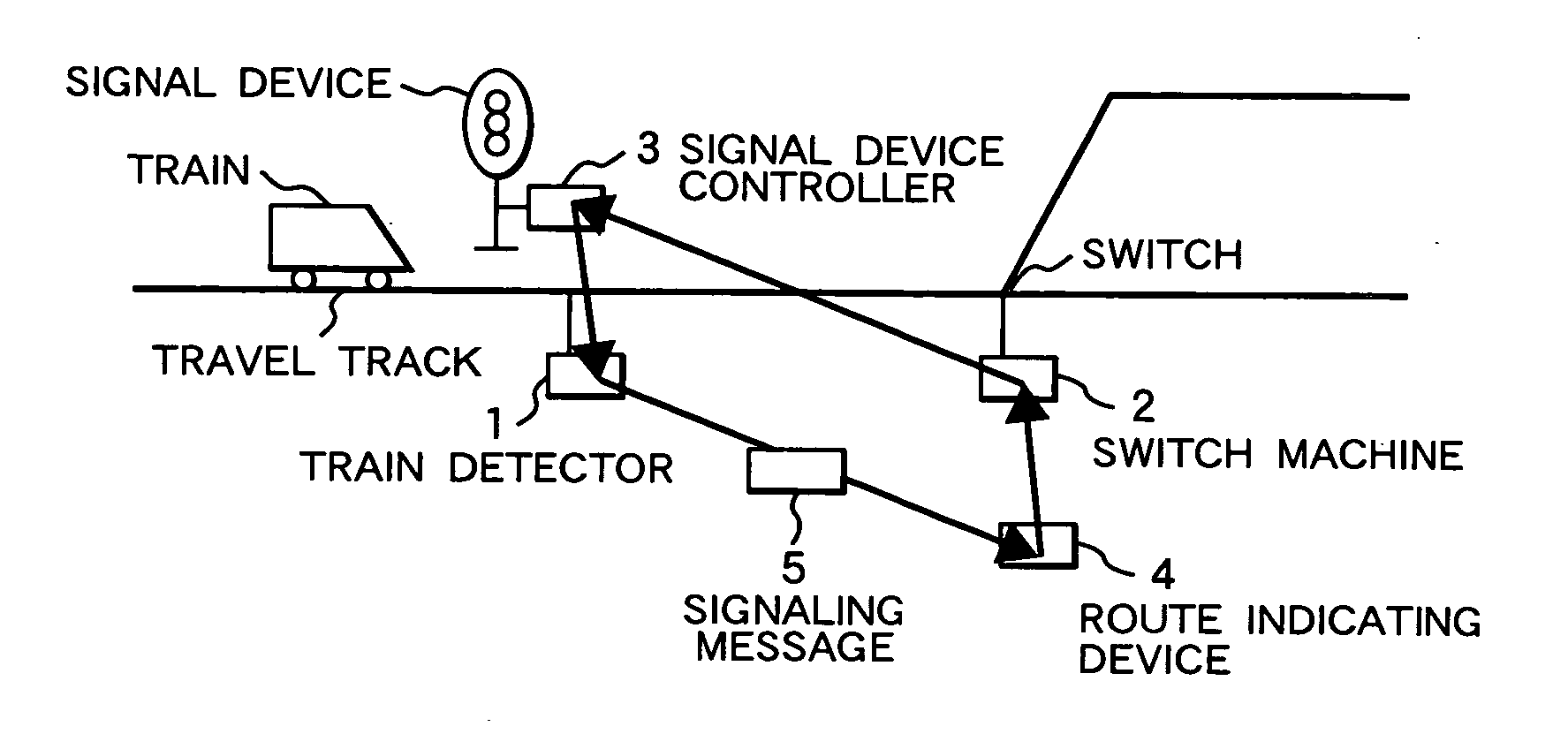
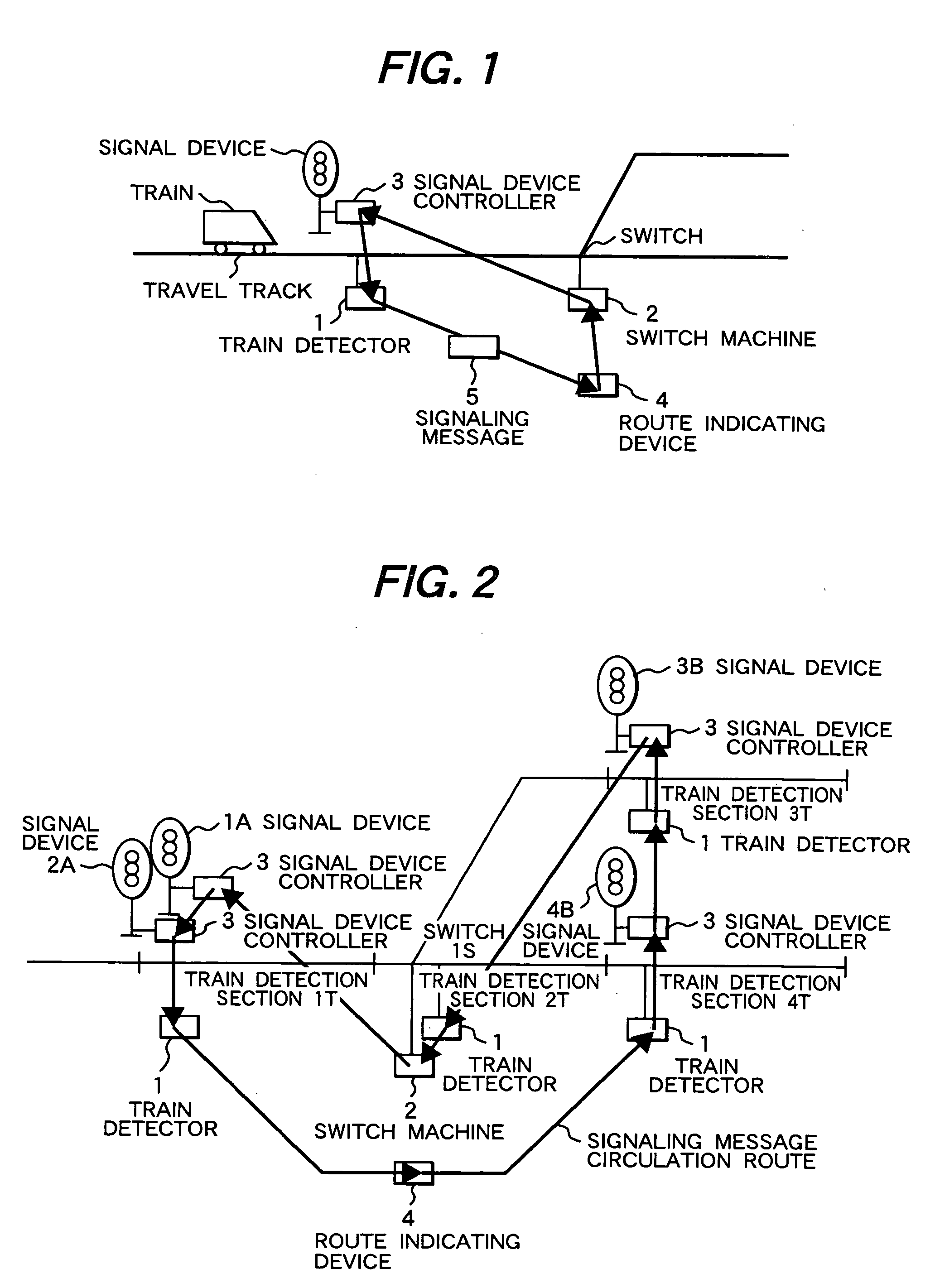
[0030] The configuration of a signaling system according to an embodiment of the present invention is shown in FIG. 1.

[0031] Railway devices that compose a signaling system of this embodiment include a train detector, point, switch machine for controlling the point, signal device, and a signal device controller for controlling the signal device.

[0032] A signaling system according to this embodiment comprises a plurality of railway devices disposed in a predetermined section, such as a train detector 1 for detecting the location of a train on the travel track, switch machine 2 for controlling a point that switches travel tracks, and a signal device controller 3 for controlling a signal device and transmitting travel permission or travel non-permission to the train; a route indicating device 4 which is disposed in the same predetermined section and indicates the direction along which the train proceeds by receiving a train route instruction from an operator or the like; and a signal...


PUM


Abstract

A message that contains train on-track information and reservation information of a train detection section and direction information and reservation information of a switch is circulated among a train detector, switch machine, signal device controller and a route indicating device. The train detector updates train on-track information of a train detection section contained in the signaling message, the switch machine updates switch direction information in the signaling message, and the route indicating device updates reservation information of the train detection section and the switch contained in the signaling message. Via the signaling message, the train detector can transmit the train detection result to the signal device controller and the route indicating device, the switch machine can transmit switch condition to the signal device controller, the route indicating device transmits route reservation to the switch machine and the signal device controller, and based on the transmitted train detection result, switch condition and route reservation condition, the signal device controller transmits travel permission or travel non-permission for the assigned route to a train.

Description

CLAIM OF PRIORITY [0001] The present application claims priority from Japanese application serial no. 2005-368989, filed on Dec. 22, 2005, the content of which is hereby incorporated by reference into this application. FIELD OF THE INVENTION [0002] The present invention relates to a signaling system used in the operation of trains, monorail, LRT (Light Rail Transit), AGT (Automated Guided Train), and the like. BACKGROUND OF THE INVENTION [0003] In the railway system, a system has been established wherein an interlocking device is conventionally used as a core of the signaling system so that it links and connects to a track circuit for detecting the presence of a train on the track, a point for switching railway tracks, and a signal device for transmitting permission for a train to proceed or not proceed along a track and does not allow a train to enter a track if there is danger of a collision or derailment. [0004] Recently, as disclosed in Japanese Patent publication No. 7-41840, a...

Claims


Application Information

Patent Timeline
Patent Type & Authority Applications(United States)
IPC IPC(8): G05D1/00
CPCB61L27/0038B61L27/20
Inventor KATSUTA, KEIICHIWATANABE, DAISUGITA, YOICHI
Owner HITACHI LTD
Learn More