Touch panel and touch liquid crystal display using the same

Inactive Publication Date: 2009-04-02
CHUNGHWA PICTURE TUBES LTD
View PDF5 Cites 34 Cited by
  • Summary
  • Abstract
  • Description
  • Claims
  • Application Information

AI Technical Summary

Benefits of technology

[0015]As the present invention adopts a polarizer to replace the glass substrate required by the touch panel, the touch panel can be directly integrated into a liquid crystal panel. Thus a structure of a touch panel is directly forme

Problems solved by technology

As the glass layer 130 of the touch panel 100 is too heavy and thick, it is not suitable for being used in portable products such as notebooks.
Furthermore, it is difficult to control the process quality due to poor adhesion of indium tin oxide (ITO) on the PET film.
Thus, the sensi

Method used


Image

  • Touch panel and touch liquid crystal display using the same
  • Touch panel and touch liquid crystal display using the same
  • Touch panel and touch liquid crystal display using the same

Examples


first embodiment

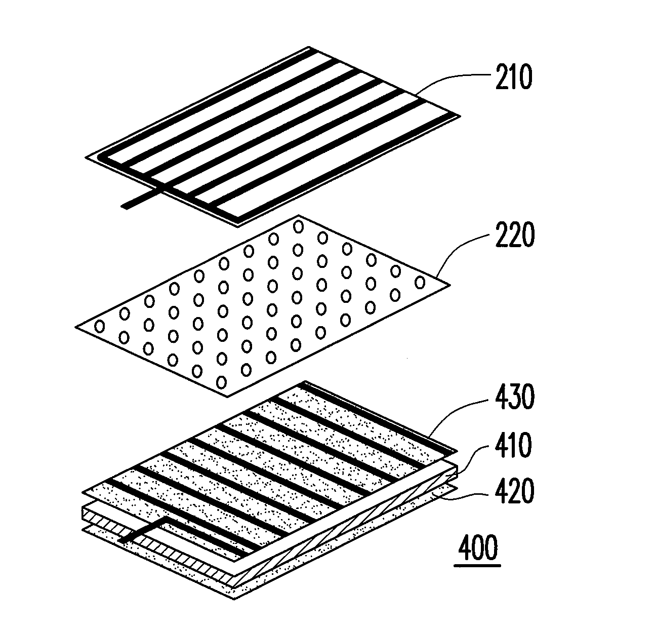
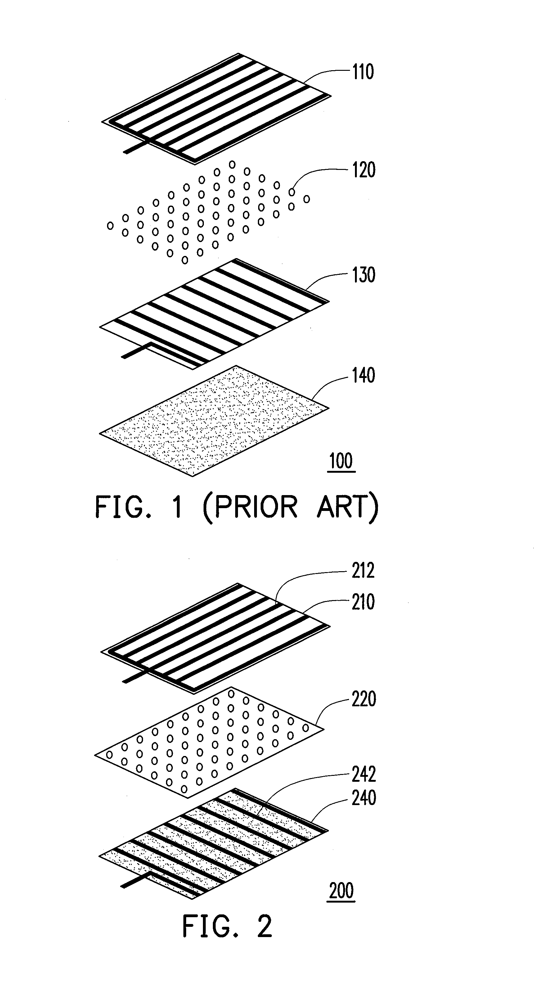
[0024]FIG. 2 is a structure diagram of a resistive touch panel according to a first embodiment of the present invention. A touch panel 200 includes a contact layer 210, an intermediate layer 220, and a polarizer 240. The intermediate layer 220 is disposed between the contact layer 210 and the polarizer 240 for spacing the contact layer 210 from the polarizer 240. The contact layer 210 can be formed by PET film, glass or polymer film, so as to serve as a region for the user to contact the touch panel. The intermediate layer 220 is formed by spacer dots for spacing the polarizer 240 from the contact layer 210 when no force is applied on the contact layer 210. The polarizer 240 has a polarization function (i.e., limiting the angle of the passing light) and an electric signal transmitting function required by the touch panel.

[0025]The polarizer 240 has a plurality of first electrodes 242, and the contact layer 210 has a plurality of second electrodes 212. The first electrodes 242 and th...

second embodiment

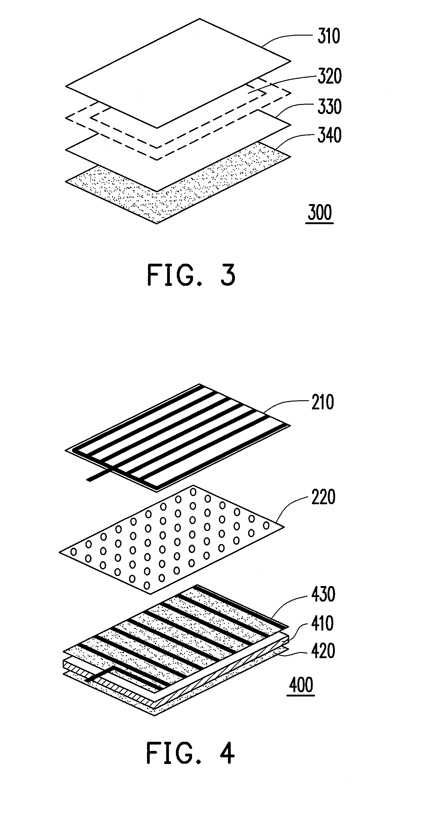
[0026]The technical method of the first embodiment can be applied in a capacitive touch panel. FIG. 3 is an architectural diagram of a capacitive touch panel according to a second embodiment of the present invention. The touch panel 300 includes a protective layer 310, an electrode pattern layer 320, a conductive layer 330, and a polarizer 340. The conductive layer 330 is disposed on the polarizer 340, and can be formed on the surface of the polarizer 340 directly by ITO. Such that the polarizer 340 has electromagnetic shielding effects. The electrode pattern layer 320 is disposed between the protective layer 310 and the conductive layer 330, and the electrode pattern layer 320 has a plurality of first electrodes and second electrodes on upper and lower surfaces thereof respectively, so as to form the desired electrode pattern. The protective layer 310 is disposed on the electrode pattern layer 320 to protect the electrode pattern layer 320.

[0027]In another embodiment of the present...

third embodiment

[0028]FIG. 4 is a structure diagram of a touch LCD according to a third embodiment of the present invention. This embodiment further illustrates the structure relationship of a resistive touch panel integrated with an LCD panel. An LCD 400 includes a lower polarizer 420, an LCD display unit 410, an upper polarizer 430, a contact layer 210, and an intermediate layer 220. The touch panel is formed by the upper polarizer 430, the contact layer 210 and the intermediate layer 220, and the structure thereof can be seen with reference to FIG. 2, which will not be repeated herein. In this embodiment, the polarizer 240 in FIG. 2 is directly used in the LCD 400 as the upper polarizer 430.

[0029]The LCD display unit 410 at least includes a first substrate, a second substrate. The upper polarizer 430 is located on a surface of the first substrate, the lower polarizer 420 is located on a surface of the second substrate, and the first substrate and the second substrate are disposed in opposite dir...


PUM


Abstract

A touch panel and a touch liquid crystal display (LCD) using the touch panel are provided. The structure of the touch panel is directly formed on an upper polarizer instead of a glass substrate. Thereby, the process of integrating the touch panel and an LCD panel is simplified and the glass substrate of the touch panel is eliminated. Thus, the cost, the thickness and the weight of the touch LCD are reduced.

Description

CROSS-REFERENCE TO RELATED APPLICATION[0001]This application claims the priority benefit of Taiwan application serial no. 96136575, filed on Sep. 29, 2007. The entirety of the above-mentioned patent application is hereby incorporated by reference herein and made a part of specification.BACKGROUND OF THE INVENTION[0002]1. Field of the Invention[0003]The present invention relates to a touch panel. More particularly, the present invention relates to a touch panel using a polarizer instead of a glass substrate and a liquid crystal display (LCD) using the touch panel (abbreviated as a touch LCD).[0004]2. Description of Related Art[0005]Touch panel is an interface tool for information exchange and is widely accepted by the public. Currently, the widely employed touch panels are mainly classified into two types, i.e., resistive touch panels and capacitive touch panels. The structure of the touch panel is mostly formed by a polyethylene terephthalate (PET) film and a layer of glass, and the...

Claims


Application Information

Patent Timeline
IPC IPC(8): G02F1/1335H03K17/975
CPCG02F1/13338G06F3/045G06F3/044G06F3/0412G06F3/0443
Inventor KO, HAN-CHINGCHANG, MIN-HUNG
Owner CHUNGHWA PICTURE TUBES LTD
Why Eureka
Try Eureka