Cooking oven

a convection oven and oven body technology, which is applied in the field of cooking ovens, can solve the problems of ineffective inability to heat up the oven, and inability to achieve simultaneous precision baking on multiple racks, so as to reduce the duty cycle, prevent the bottom burning of food products, and increase the duty cycle

Active Publication Date: 2009-03-12
HINES JR ROBERT STICKLEY
View PDF26 Cites 13 Cited by
  • Summary
  • Abstract
  • Description
  • Claims
  • Application Information

AI Technical Summary

Benefits of technology

[0007]The present invention, in one of its most preferred embodiments comprises an oven structure which provides for an oven unit comprising a single or multiple (any number) side by side ovens, wherein the multiple ovens are independently operable and are separated by generally vertical, hinged partition(s) whereby upon swinging one or more partitions back to adjacent the rear of one or more adjacent ovens the oven structure may then function as one or more large ovens, and which further provides for highly controlled heating of each cooking chamber by means of a tangential fan for each chamber with air flow therefrom directed over upper electrical heating elements by means of flow director structure ensuring laminar flow and evenness of heat transfers, wherein the flow director also functions as a radiant heat shield or occluder which is operator movable to either expose or occlude the radiant heat to each cooking chamber from the upper elements depending on the need to roast, bake, or broil the food product. Also provided are lower electrical heating elements positioned below ceramic cooking surfaces for ensuring evenness of radiant heat transfer therefrom. Also provided for is operator controlled top vs. bottom heating using a slide control that reciprocally affects the duty cycle of the top and bottom electrical heating elements, further allowing precision baking control.
[0008]The present oven structure design addresses the aforementioned prior difficulties and in addition, the design concept extends the side walls of the oven and diminishes the vertical oven height, and provides a hinged moveable vertical partition to enable the operator to vary the cooking chamber size for smaller or larger products. This allows for the oven to be employed as a single larger oven or as two or more smaller ovens. Also, independent controls for these partitioned cooking chambers enable the user to perform independent cooking tasks in each separate cooking chamber.
[0010]The flow director is constructed to function also as a radiant heat occluder to either block or expose the cooking product to direct radiant heat from the upper heating elements depending on the cooking task desired. For example, the air flow director can serve as a radiant shield for the top elements, thereby ensuring evenest in heating but can be repositioned to expose the top heating elements to the food product as would be necessary, for example for broiling. Bottom heat is provided by heating elements preferably beneath a large ceramic plate which forms the floor or bottom wall of the oven cooking chamber on which plate the food product may be placed either directly as with bread or indirectly as in a cooking vessel. The ceramic or metal plate functions as a heat sink and radiates heat evenly. A ceramic plate is preferred since it is a poor heat conductor and thus prevents burning of the bottom of the food product.
[0011]All of the above features of the present invention, in combination, ensure an even heat distribution to the food product. Also, the ultimate in precision baking is the ability to reciprocally adjust the heat delivery from upper and lower heating elements of each oven. This is accomplished by the present invention by means of, e.g., a slide switch (variable resistor) and an appropriate electrical circuit that increases or decreases the cycle time to the upper and lower heating elements in a reciprocal fashion. For example, adjusting the switch upwardly would concomitantly increase the duty cycle of the upper elements and decrease the duty cycle of the lower elements. Preset temperature would be maintained thereby but the top of the product would be exposed to more heat, much like moving the conventional oven rack up or down. Examples would be cooking a steak with the slide switch in the full up position with the heat being generated exclusively by the upper elements such as to effect broiling. In cooking a pizza for example, the switch would be far down to effectively brown the crust.
[0012]The present ovens can be mounted under shelf, or over the stove cooking surface with appropriate venting provided, or over the counter top. This makes the baking process more convenient in minimizing bending or stooping and allows the user to more easily produce the exact “brownness” of the cooked products especially breads, particularly where the provision of a large glass door enhances visualization. In this regard, ease of visualization is provided by the oven being just below eye level and by large transparent doors.

Problems solved by technology

Much oven usage involves baking, roasting or broiling of smaller size or number of food products whereby utilization of the large standard oven cavity becomes energy inefficient.
Attempts at simultaneous precision baking on multiple racks is usually futile because of the unevenness in heat transfer excepting perhaps for ovens with “pure” or “European style” convection.
Attempts have been made to “fine tune” this “sweet spot” by placing the racks at different heights, however, many conventional ovens still have a tendency to over cook or over brown the food product at the rear of the oven.
This can be due to excessive air leaks in the oven door, excessive airflow over the product next to fan intake, or even opening the oven door multiple times to check on the product being baked.

Method used


Image

  • Cooking oven
  • Cooking oven
  • Cooking oven

Examples


Embodiment Construction

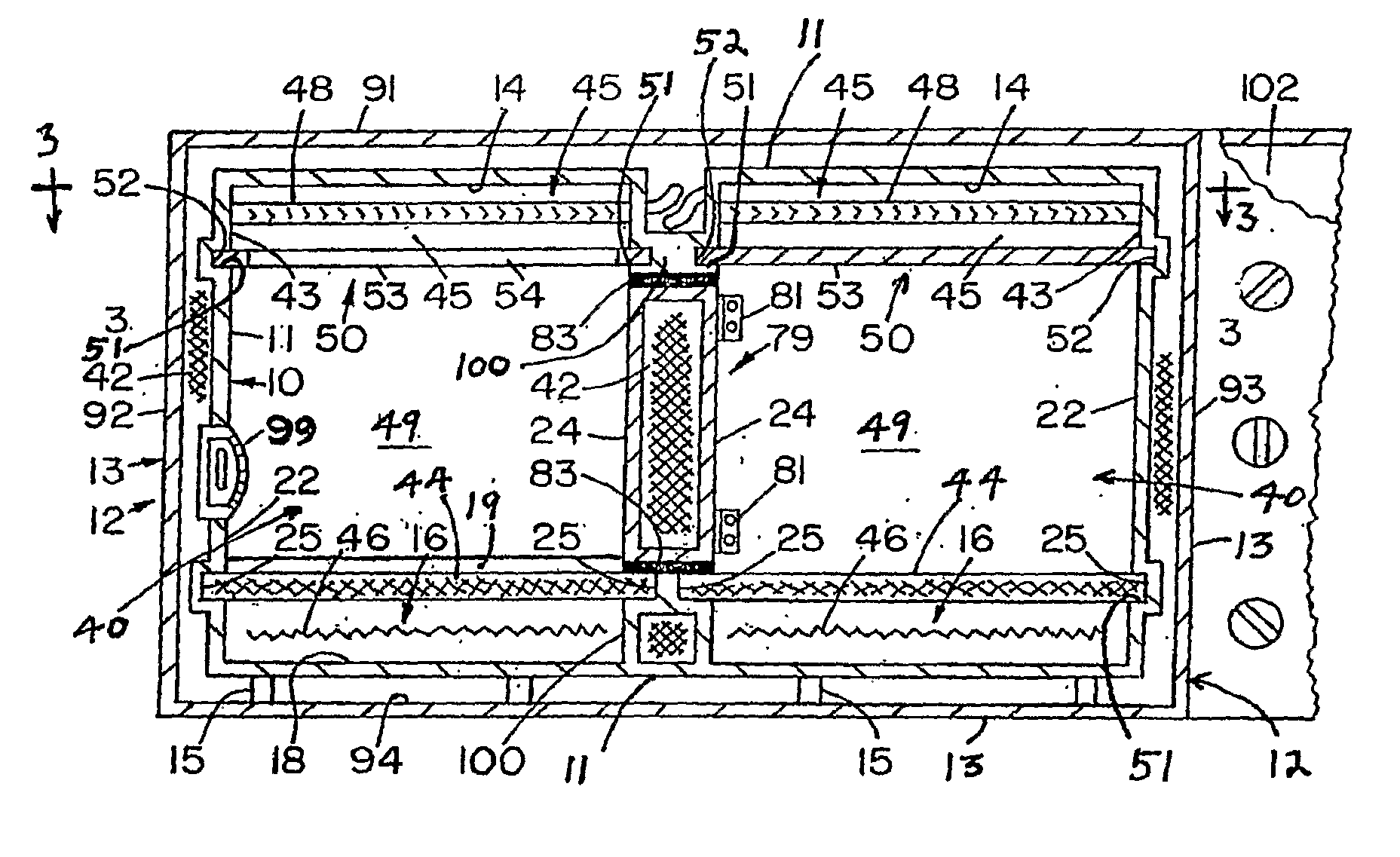
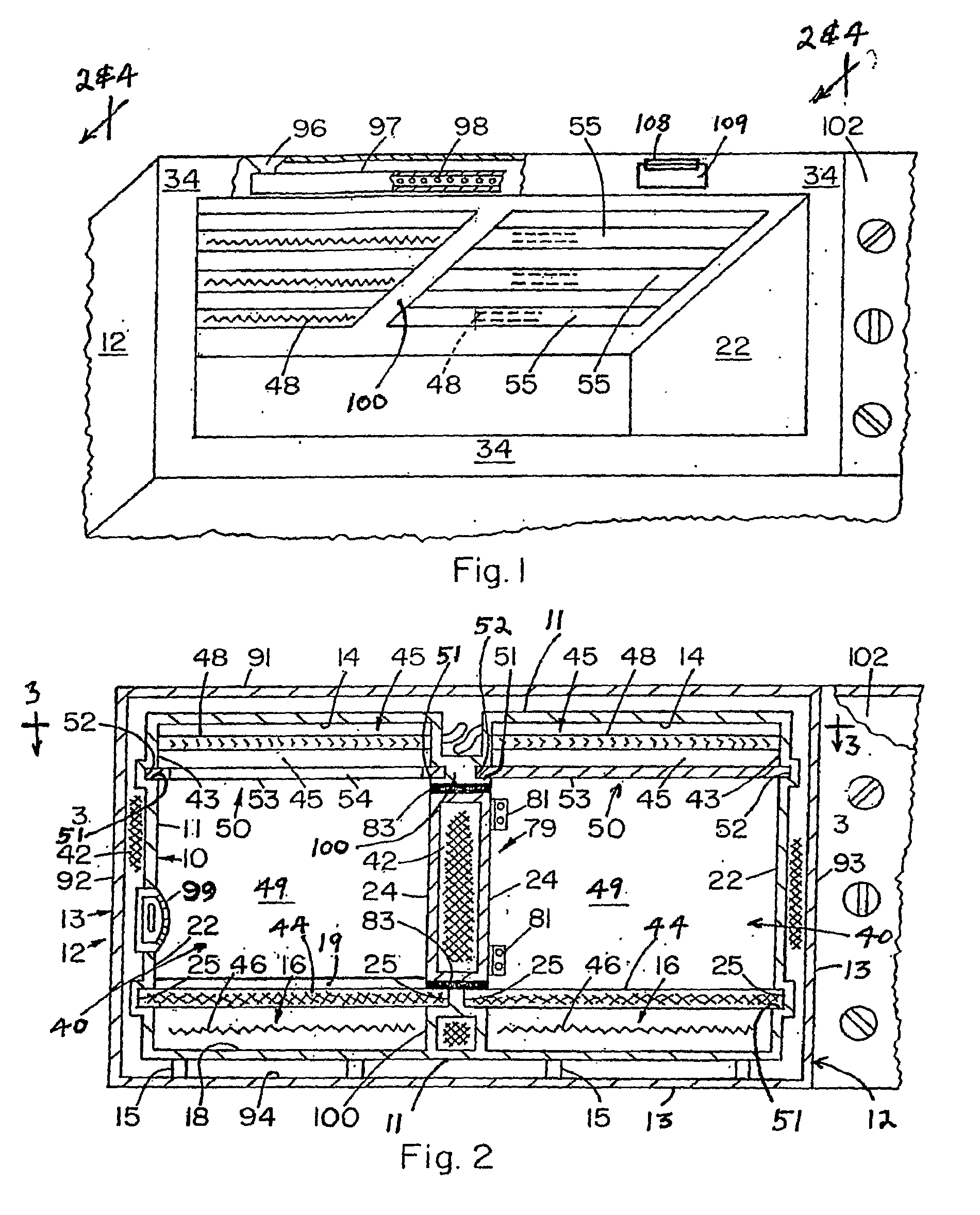
[0030]Referring to the drawings which represent the preferred and best mode for practicing the present invention, the various wall structures are shown as monolithic, however, fabrication in sections of these structures in conventional manner can be employed. As shown, the present cooking oven structure comprises a single (FIG. 1) or side by side multiple ovens (FIGS. 2-10), wherein each oven comprises spaced inner 10 and outer 12 metal housings formed respectively by first wall means 11 and second wall means 13. First wall means 11 provides the structural elements of a ceiling 14, a floor 18, opposing side walls 22, 24, a back wall 30, and front wall portions 34 provided with a hinged access door 38.

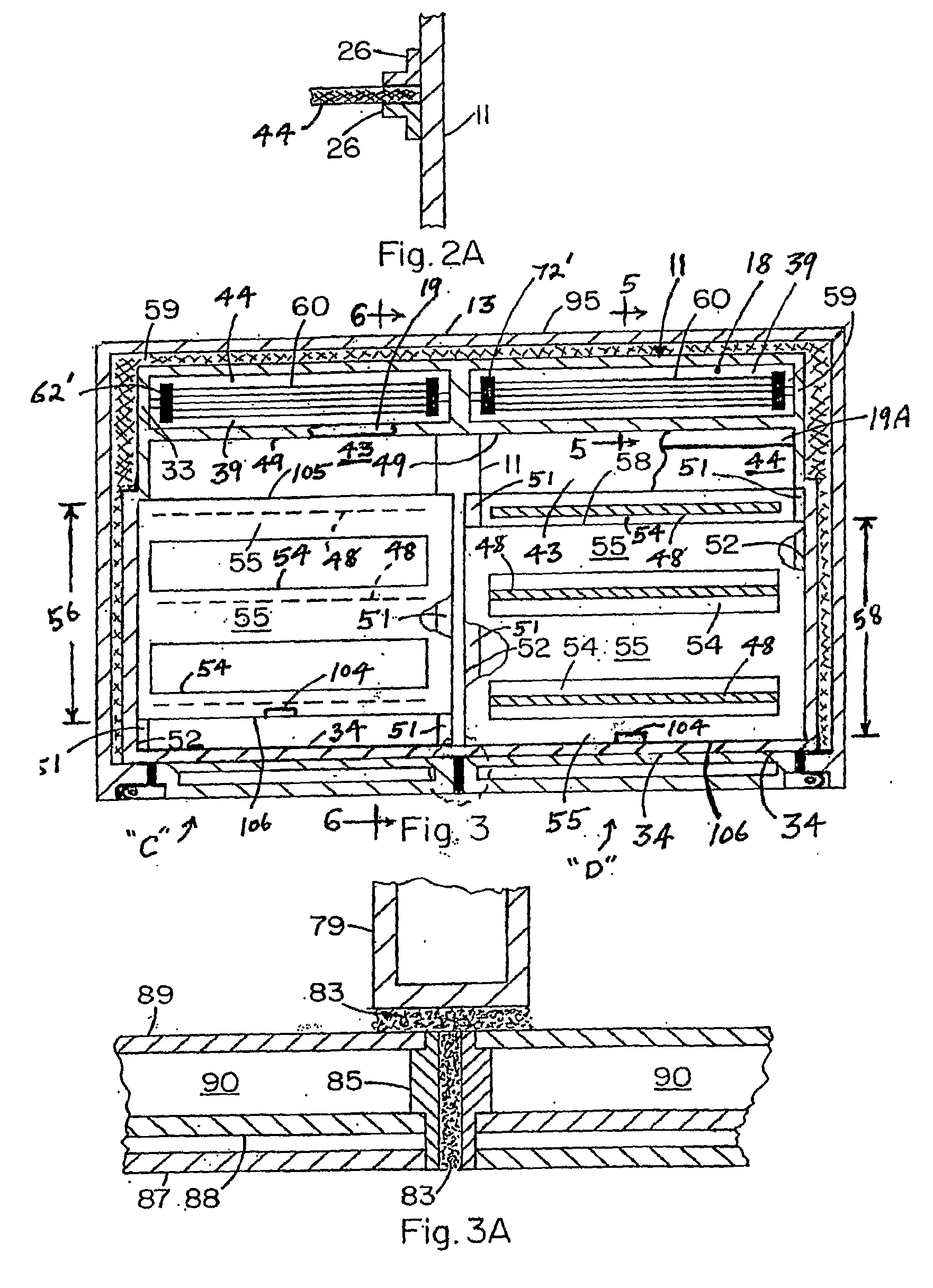
[0031]For each oven, the combination of an upper heating cavity 45 communicating with a circulating air feed channel generally designated 39 is formed (for oven “C” see FIGS. 3 and 6) by side walls 22 and 24, back wall 30 and ceiling 14 of first wall means 11, by third wall means 41 hav...


PUM


Abstract

A cooking structure which provide for two or more side-by-side ovens separated by vertical, movable, hinged partition(s) whereby the oven structure may function as one large oven or as two or more smaller independent ovens, wherein for each oven a tangential fan blows air substantially evenly over upper electrical heating elements strung generally from side-to-side of the oven, wherein a flow director (baffle) structure functions as a radiant heat shield which is operator movable to either expose to or occlude from the oven cooking chamber the direct radiation from its heating elements, depending on the need to roast, bake, or broil the food product. Also provided are lower electrical heating elements positioned below a ceramic cooking surface for ensuring evenness of radiant heat transfer therefrom. Also provided is operator controlled top vs. bottom heating using a slide control that reciprocally affects the duty cycle of the top and bottom electrical heating elements, further allowing precision baking control.

Description

[0001]This application is a Continuation-in-Part of Applicant's pending application Ser. No. 11 / 347,982 filed 2-6-06 and titled “COOKING OVEN”, and Applicant claims priority under 35 U.S.C. 119(e)(1) based on Applicants Provisional U.S. Patent Application Ser. No. 60 / 661,618 filed Mar. 14, 2005 and titled “CONCEPT DESIGN FOR COMMERCIAL STYLE HOME BAKING DEVICE / OVEN”, on Provisional 60 / 693,882 filed Jun. 24, 2005 titled “CONCEPT OVEN DESIGN”, and on Provisional 60 / 839,643 filed Aug. 23, 2006 and titled “COOKING OVEN”.BACKGROUND OF THE INVENTION[0002]1. Field[0003]The present invention is directed to electrically heated convection baking ovens and the like and particularly concerns, in preferred embodiments, operator control of radiant heat emanating from heating elements and directed down into the oven cooking chamber, specially constructed and functional heated air circulating means for providing more uniform heat transfer throughout the cooking chamber, an upper heating element and...

Claims


Application Information

Patent Timeline
Patent Type & Authority Applications(United States)
IPC IPC(8): A21B1/22A21B3/00
CPCF24C15/325F24C7/087
Inventor HINES, JR., ROBERT STICKLEY
Owner HINES JR ROBERT STICKLEY
Why Eureka
Try Eureka