Cooking oven

a convection oven and oven body technology, which is applied in the field of cooking ovens, can solve the problems of ineffective inability to heat up the oven, and inability to achieve simultaneous precision baking on multiple racks, etc., to achieve the effect of reducing the duty cycle, preventing the bottom burning of food products, and increasing the duty cycl

Inactive Publication Date: 2007-05-17
HINES ROBERT STICKLEY JR
View PDF6 Cites 24 Cited by
  • Summary
  • Abstract
  • Description
  • Claims
  • Application Information

AI Technical Summary

Benefits of technology

[0010] The flow director is constructed to function also as a radiant heat occluder to either block or expose the cooking product to direct radiant heat from the upper heating elements depending on the cooking task desired. For example, the air flow director can serve as a radiant shield for the top elements, thereby ensuring evenest in heating but can be repositioned to expose the top heating elements to the food product as would be necessary, for example for broiling. Bottom heat is provided by heating elements preferably beneath a large ceramic plate which forms the floor or bottom wall of the oven cooking chamber on which plate the food product may be placed either directly as with bread or indirectly as in a cooking vessel. The ceramic or metal plate functions as a heat sink and radiates heat evenly. A ceramic plate is preferred since it is a poor heat conductor and thus prevents burning of the bottom of the food product.
[0011] All of the above features of the present invention, in combination, ensure an even heat distribution to the food product. Also, the ultimate in precision baking is the ability to reciprocally adjust the heat delivery from upper and lower heating elements of eac

Problems solved by technology

Much oven usage involves baking, roasting or broiling of smaller size or number of food products whereby utilization of the large standard oven cavity becomes energy inefficient.
Attempts at simultaneous precision baking on multiple racks is usually futile because of the unevenness in heat transfer excepting perhaps for ovens with “pure” or “European style” convection.
Attempts have been made

Method used


Image

  • Cooking oven
  • Cooking oven
  • Cooking oven

Examples


Embodiment Construction

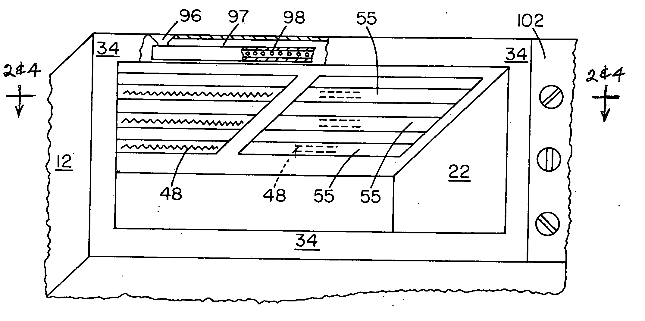
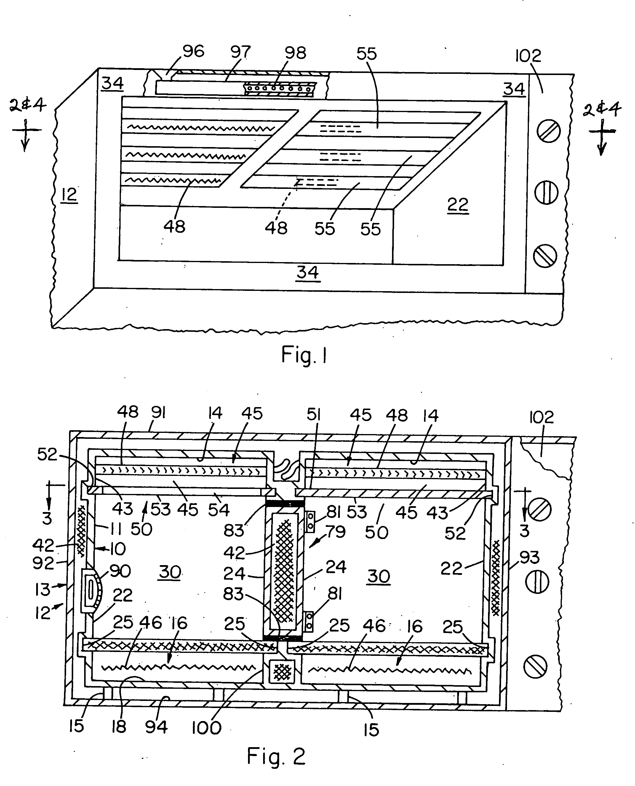
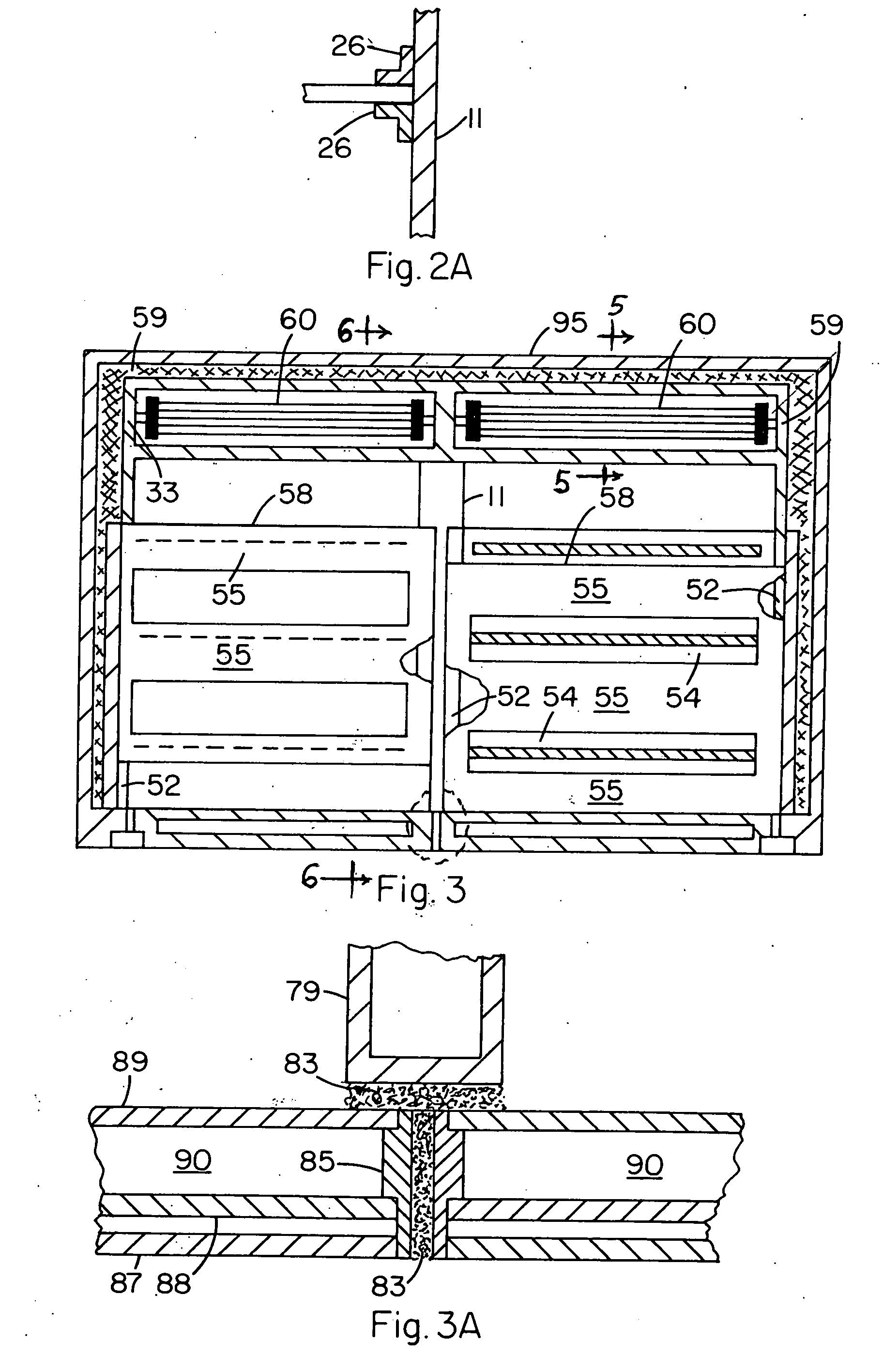
[0027] Referring to the drawings the present cooking oven structure comprises a single or side by side multiple ovens, wherein each oven comprises spaced inner 10 and outer 12 metal housings formed respectively by first wall means 11 and second wall means 13. First wall means 11 provides the structural elements of a ceiling 14, a floor 18, opposing side walls 22, 24, a back wall 30, and front wall portions 34 provided with a hinged access door 38. An upper heating cavity 45 and a circulating air feed channel 47 combination generally designated 39 is formed by third wall means 41 having a generally horizontal upper section 43 spaced inwardly from ceiling 14 and by a general vertical side section 49 spaced inwardly from the back wall 30 of the inner housing.

[0028] A heat sink ceramic or steel plate means 44 is adapted to provide a predeterminable heat supply and is spaced upwardly from floor 18 and forms with wall means 11 a lower heating cavity 16. Section 49 is spaced upwardly from...


PUM


Abstract

A cooking structure which provide for two or more side-by-side ovens separated by vertical, movable, hinged partition(s) whereby the oven structure may function as one large oven or as two or more smaller independent ovens, wherein for each oven a tangential fan blows air substantially evenly over upper electrical heating elements strung generally from side-to-side of the oven, wherein a flow director functions as a radiant heat shield which is operator movable to either expose to or occlude from the oven cooking chamber to direct radiation from its heating elements depending on the need to roast, bake, or broil the food product. Also provided are lower electrical heating elements positioned below a ceramic cooking surface for ensuring evenness of radiant heat transfer therefrom. Also provided for is operator controlled top vs. bottom heating using a slide control that reciprocally affects the duty cycle of the top and bottom electrical heating elements, further allowing precision baking control.

Description

[0001] This application claims priority under 35 U.S.C. 119(e)(1) based on Applicants Provisional U.S. patent application Ser. No. 60 / 661,618 filed Mar. 14, 2005 and titled “CONCEPT DESIGN FOR COMMERCIAL STYLE HOME BAKING DEVICE / OVEN”.BACKGROUND OF THE INVENTION [0002] 1. Field [0003] The present invention is directed to electrically heated convection baking ovens and the like and particularly concerns, in preferred embodiments, operator control of radiant heat emanating from heating elements and directed down into the oven cooking chamber, specially constructed and functional heated air circulating means for providing more uniform heat transfer throughout the cooking chamber, an upper heating element and a lower heating element with a ceramic or metal heat sink, specially designed partition or divider means for quickly and easily converting the oven cooking chamber from a single chamber to multiple chambers and vise versa, and in a most preferred embodiment uniquely functional elec...

Claims


Application Information

Patent Timeline
IPC IPC(8): F27D11/00
CPCF24C7/087F24C15/325
Inventor HINES, ROBERT STICKLEY JR.
Owner HINES ROBERT STICKLEY JR
Why Eureka
Try Eureka