Magnetic resonance imaging apparatus and navigator data analyzing method
- Summary
- Abstract
- Description
- Claims
- Application Information
AI Technical Summary
Benefits of technology
Problems solved by technology
Method used
Image
Examples
first embodiment
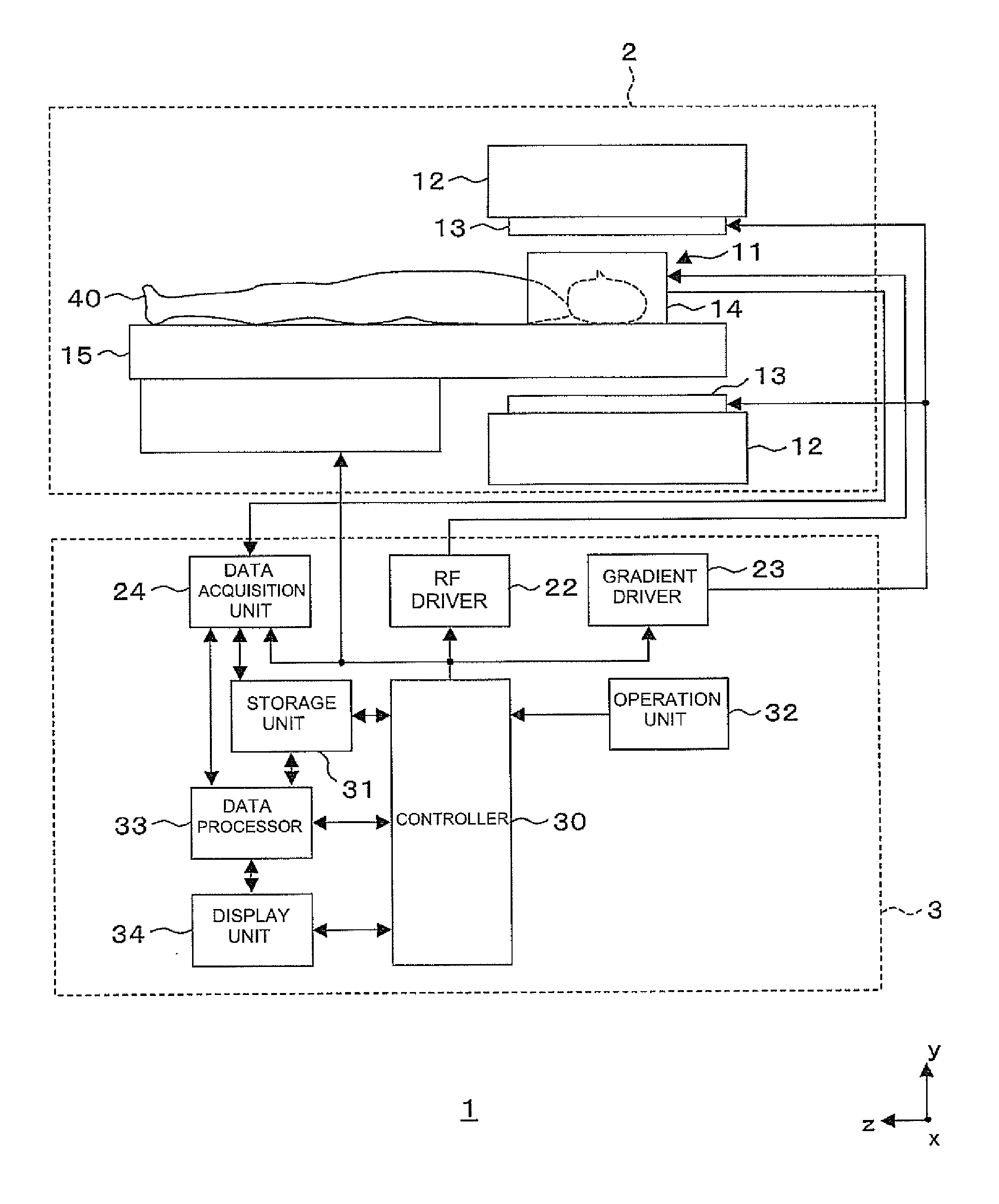
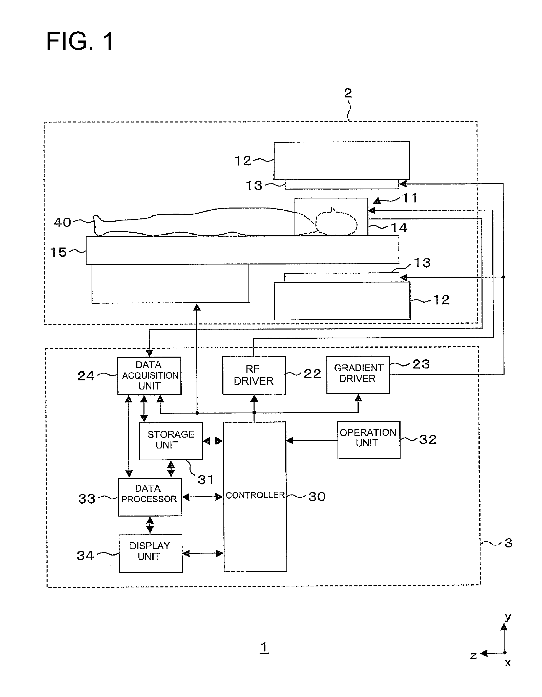
[0049]FIG. 1 is a constructional diagram showing a construction of a magnetic resonance imaging apparatus constituted of an RF coil unit employed in a first embodiment according to the invention. The present apparatus is one example of embodiments according to the invention.
[0050]As shown in FIG. 1, the magnetic resonance imaging apparatus 1 has a scan section 2 and an operation console section 3. Here, the scan section 2 has a static magnetic field magnet unit 12, a gradient coil unit 13, an RF coil unit 14 and a cradle 15. The operation console section 3 has an RF driver 22, a gradient driver 23, a data acquisition unit 24, a controller 30, a storage unit 31, an operation unit 32, a data processor 33 and a display unit 34.
[0051]The scan section 2 will be explained.
[0052]As shown in FIG. 1, the scan section 2 includes a static magnetic field space 11 in which an imaging slice area in a subject 40 is held or accommodated. The scan section 2 applies RF pulses to the corresponding ima...
second embodiment
[0116]FIG. 11 is a block diagram showing a construction of a data processor 33 employed in a second embodiment according to the invention. The present data processor is one example illustrative of the embodiment of the invention.
[0117]The second embodiment is identical to the first embodiment in terms of the portions other than a range setting part 335 corresponding to the construction of a magnetic resonance imaging apparatus 1. Therefore, the description of dual portions will be omitted.
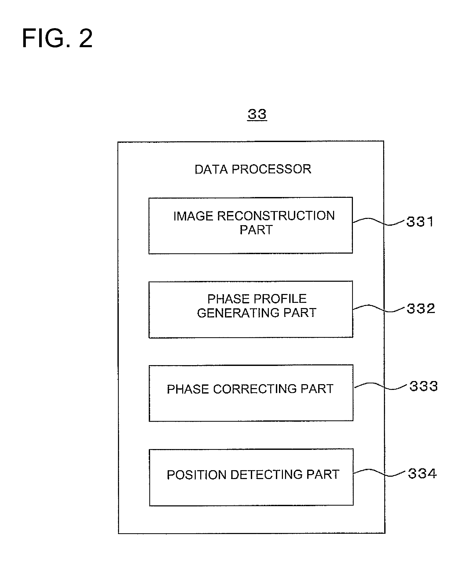
[0118]As shown in FIG. 11, the data processor 33 has the image reconstruction part 331, phase profile generating part 332, phase correcting part 333, position detecting part 334 and range setting part 335.
[0119]The range setting part 335 sets, for example, a range for detecting a position L of a boundary b between tissues in a subject 40 to a phase profile subjected to the correction by the phased correcting part 333. In the present embodiment, an operator recognizes and decides, through the corres...
third embodiment
[0134]FIG. 15 is a block diagram showing a construction of a data processor 33 employed in a third embodiment according to the invention. The present data processor is one example illustrative of the embodiment of the invention.
[0135]The third embodiment is identical to the second embodiment in terms of the portions other than a phase profile smoothing part 336 corresponding to the construction of a magnetic resonance imaging apparatus 1. Therefore, the description of dual portions will be omitted.
[0136]As shown in FIG. 15, the data processor 33 has the image reconstruction part 331, phase profile generating part 332, phase correcting part 333, position detecting part 334, range setting part 335 and phase profile smoothing part 336.
[0137]When, for example, a phase profile subjected to correction by the phase correcting part 333 is discontinuous, the phase profile smoothing part 336 smoothes the phase profile. In the present embodiment, the phase profile smoothing part 336 filters, f...
PUM
 Abstract
Description
Claims
Application Information
 - R&D
- Intellectual Property
- Life Sciences
- Materials
- Tech Scout
- Unparalleled Data Quality
- Higher Quality Content
- 60% Fewer Hallucinations
Browse by: Latest US Patents, China's latest patents, Technical Efficacy Thesaurus, Application Domain, Technology Topic, Popular Technical Reports.
© 2025 PatSnap. All rights reserved.Legal|Privacy policy|Modern Slavery Act Transparency Statement|Sitemap|About US| Contact US: help@patsnap.com


