Magnetic resonance imaging apparatus and navigator data analyzing method

a magnetic resonance imaging and navigator data technology, applied in the field of magnetic resonance imaging (mri) apparatus and navigator data analysis, can solve the problems of difficult to obtain a stable analytic and degrade the quality of images, and achieve the effect of preventing image deterioration, stable analytic result, and stable navigator data analytic resul

Active Publication Date: 2010-08-24
GE MEDICAL SYST GLOBAL TECH CO LLC
View PDF22 Cites 3 Cited by
  • Summary
  • Abstract
  • Description
  • Claims
  • Application Information

AI Technical Summary

Benefits of technology

[0009]It is desirable that the problem described previously is solved. Thus, the invention provides a magnetic resonance imaging apparatus capable of preventing deterioration in image by obtaining a stable analytic result of navigator data, and a navigator data analyzing method capable of obtaining a stable analytic result of navigator data.
[0010]Further, the invention provides a magnetic resonance imaging apparatus capable of preventing image deterioration by obtaining a stable analytic result of navigator data even when an imaging slice based on an imaging scan and a navigator area have overlapped, and a navigator data analyzing method capable of obtaining a stable analytic result of navigator data.
[0027]According to the invention, there can be provided a magnetic resonance imaging apparatus and a navigator data analyzing method both capable of obtaining a stable analytic result of navigator data even when an imaging slice based on an imaging scan and a navigator area overlap.

Problems solved by technology

When, for example, the heart or abdominal region of the subject is imaged, body motion artifacts occur due to body motion such as breathing exercises, cardiac motion or the like, thus degrading the quality of the image.
In doing so, it became difficult to obtain a stable analytic result by the conventional navigator data analyzing method shown above.

Method used


Image

  • Magnetic resonance imaging apparatus and navigator data analyzing method
  • Magnetic resonance imaging apparatus and navigator data analyzing method
  • Magnetic resonance imaging apparatus and navigator data analyzing method

Examples


first embodiment

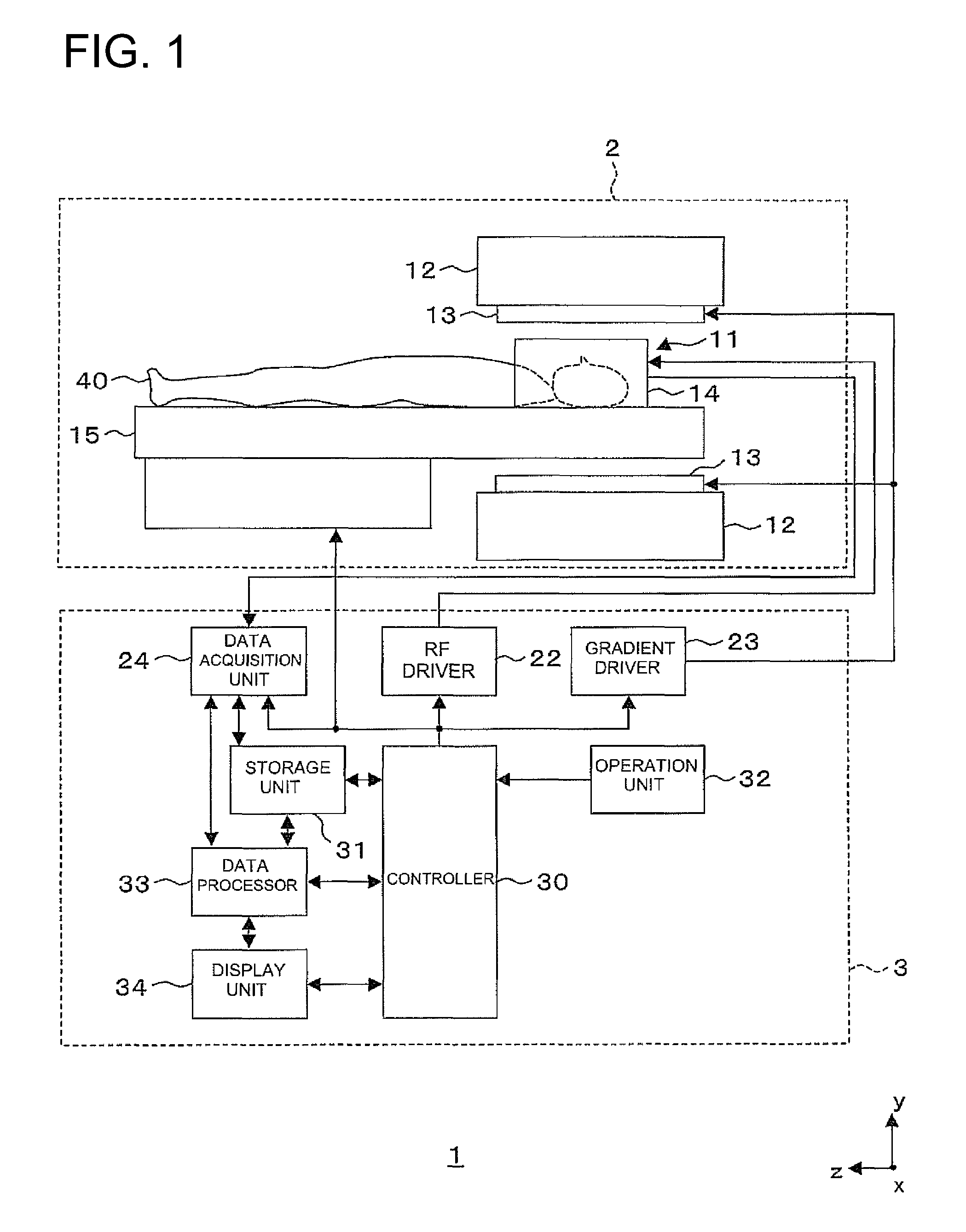
[0049]FIG. 1 is a constructional diagram showing a construction of a magnetic resonance imaging apparatus constituted of an RF coil unit employed in a first embodiment according to the invention. The present apparatus is one example of embodiments according to the invention.

[0050]As shown in FIG. 1, the magnetic resonance imaging apparatus 1 has a scan section 2 and an operation console section 3. Here, the scan section 2 has a static magnetic field magnet unit 12, a gradient coil unit 13, an RF coil unit 14 and a cradle 15. The operation console section 3 has an RF driver 22, a gradient driver 23, a data acquisition unit 24, a controller 30, a storage unit 31, an operation unit 32, a data processor 33 and a display unit 34.

[0051]The scan section 2 will be explained.

[0052]As shown in FIG. 1, the scan section 2 includes a static magnetic field space 11 in which an imaging slice area in a subject 40 is held or accommodated. The scan section 2 applies RF pulses to the corresponding ima...

second embodiment

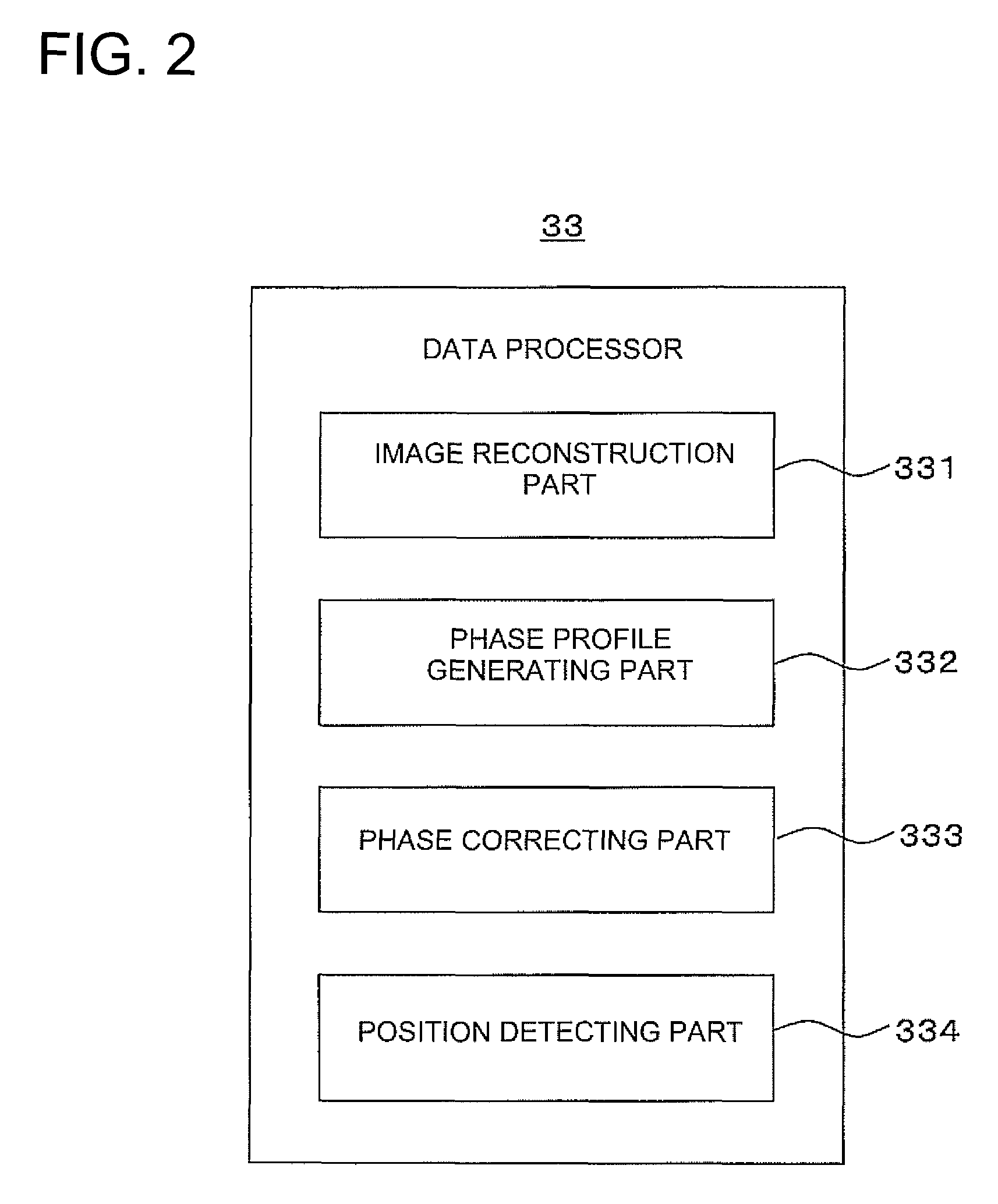
[0117]FIG. 11 is a block diagram showing a construction of a data processor 33 employed in a second embodiment according to the invention. The present data processor is one example illustrative of the embodiment of the invention.

[0118]The second embodiment is identical to the first embodiment in terms of the portions other than a range setting part 335 corresponding to the construction of a magnetic resonance imaging apparatus 1. Therefore, the description of dual portions will be omitted.

[0119]As shown in FIG. 11, the data processor 33 has the image reconstruction part 331, phase profile generating part 332, phase correcting part 333, position detecting part 334 and range setting part 335.

[0120]The range setting part 335 sets, for example, a range for detecting a position L of a boundary b between tissues in a subject 40 to a phase profile subjected to the correction by the phased correcting part 333. In the present embodiment, an operator recognizes and decides, through the corres...

third embodiment

[0135]FIG. 15 is a block diagram showing a construction of a data processor 33 employed in a third embodiment according to the invention. The present data processor is one example illustrative of the embodiment of the invention.

[0136]The third embodiment is identical to the second embodiment in terms of the portions other than a phase profile smoothing part 336 corresponding to the construction of a magnetic resonance imaging apparatus 1. Therefore, the description of dual portions will be omitted.

[0137]As shown in FIG. 15, the data processor 33 has the image reconstruction part 331, phase profile generating part 332, phase correcting part 333, position detecting part 334, range setting part 335 and phase profile smoothing part 336.

[0138]When, for example, a phase profile subjected to correction by the phase correcting part 333 is discontinuous, the phase profile smoothing part 336 smoothes the phase profile. In the present embodiment, the phase profile smoothing part 336 filters, f...


PUM


Abstract

A magnetic resonance imaging apparatus executes scans for executing a navigator sequence for acquiring as navigator data a magnetic resonance signal from a navigator area containing tissues body-moved in a subject and executing an imaging sequence for acquiring a magnetic resonance signal from an imaging area as imaging data at the subject, thereby to generate an image with respect to the imaging area. The magnetic resonance imaging apparatus includes, a phase profile generating part which generates a phase profile so as to show a relationship between a phase of the navigator data and a position of the navigator area, a phase correcting part which corrects folding back of the phase profile generated by the phase profile generating part, and a position detecting part which detects a position of a tissue body-moved in the navigator area, based on the phase profile corrected by the phase correcting part.

Description

CROSS REFERENCE TO RELATED APPLICATIONS[0001]This application claims the benefit of Japanese Patent Application No. 2007-221489 filed Aug. 28, 2008, which is hereby incorporated by reference in its entirety.BACKGROUND OF THE INVENTION[0002]The subject matter disclosed herein relates to a magnetic resonance imaging (MRI) apparatus and a navigator data analyzing method, and particularly to a magnetic resonance imaging apparatus which executes scans for transmitting RF pulses to a subject within a static magnetic field space and acquiring magnetic resonance signals from the subject thereby to produce an image about the subject, and a navigator data analyzing method for analyzing navigator data obtained by executing scans, for detecting the position of each tissue in a subject.[0003]A magnetic resonance imaging apparatus executes scans for applying an electromagnetic wave to a subject lying within a static magnetic field space thereby to excite spins of proton in the subject by a nuclea...

Claims


Application Information

Patent Timeline
Patent Type & Authority Patents(United States)
IPC IPC(8): G01V3/00
CPCG01R33/5676G01R33/56509
Inventor KANDA, KENICHIIWADATE, YUJI
Owner GE MEDICAL SYST GLOBAL TECH CO LLC
Why Eureka
Try Eureka