Image signal processing device and image signal processing method

a signal processing device and image signal technology, applied in the direction of color signal processing circuits, instruments, television systems, etc., can solve the problems of color hue rotation and color blown out, insufficient high luminance resolution in this region, and influence of high-luminance portions, etc., to achieve superior image signal processing apparatus, superior image signal processing method, superior image signal processing

Active Publication Date: 2009-03-12
SONY CORP
View PDF5 Cites 28 Cited by
  • Summary
  • Abstract
  • Description
  • Claims
  • Application Information

AI Technical Summary

Benefits of technology

[0052]In such a case, when the digital camera is in a monitoring mode, Δγ correction is not used, the luminance signal to be output is clipped at 255 gradations, and the information in the high-luminance portion is lost. However, since it is not that an image is stored, no particular problem is posed even if the reduction in the system control load takes a higher priority.
[0053]According to the present invention, it is possible to provide a superior image signal processing apparatus and a superior image signal processing method capable of converting an image signal obtained from a solid-state image-capturing device into an image signal composed of a luminance signal and color-difference signals (Y / Cr / Cb, etc.) having an appropriate dynamic range.
[0028]Another object of the present invention is to provide a superior image signal processing apparatus and a superior image signal processing method capable of widening a dynamic range by setting an appropriate signal processing range for each sensitivity setting of a digital camera and by effectively using the output range that is originally possessed by a solid-state image-capturing device and capable of obtaining an image having less color hue rotation.
[0055]According to the present invention, since a luminance signal and color-difference signals are generated after the output level (bit length) in an RGB γ correction process are expanded, with regard to the color-difference signals, the dynamic range is improved and color rotation is reduced due to the fact that clip caused by RGB γ correction of the related art is lost. Regarding color rotation and the color dynamic range, clipping is applied to color-difference signals in the course of performing color difference conversion on bit-expanded RGB γ output. Having a sufficient RGB γ output level enables large suppression of color rotation and expansion of the dynamic range to be implemented. The luminance signal is subjected to a non-linear process exclusively used for luminance so as to fit into 255 gradations, making it possible to obtain a luminance signal having a wide dynamic range.
[0056]The system control load of gradation conversion for high sensitivity of a luminance signal is higher than that of usual gradation conversion. Therefore, in the image-capturing apparatus according to the present invention incorporating an image signal process, gradation conversion for high sensitivity is applied only when a still image is to be captured and is not applied in the monitoring mode in which only finder output is performed, thereby making it possible to reduce the system control load.

Problems solved by technology

However, since gradation compression is performed only in the high-luminance region, the high luminance resolution becomes insufficient in this region.
For example, in a captured image containing many high-luminance portions, it is a problem that influence of the high-luminance portions appears.
In the RGB γ correction of the related art in which 8-bit γ output is made with respect to 8-bit γ input, due to the fact that an image-plane formation γ curve is separated from a power γ (refer to FIG. 6) and due to an RGB γ curve and clipping in a color difference matrix, there are problems in that color hue rotation and color blown out occur.

Method used


Image

  • Image signal processing device and image signal processing method
  • Image signal processing device and image signal processing method
  • Image signal processing device and image signal processing method

Examples


Embodiment Construction

[0093]An embodiment of the present invention will be described below in detail with reference to the drawings.

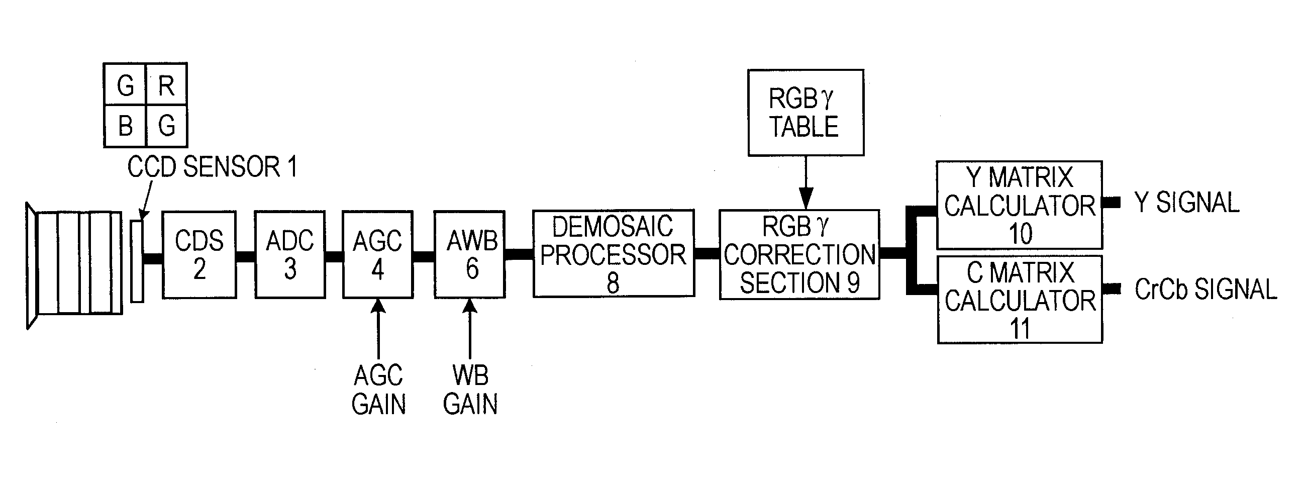
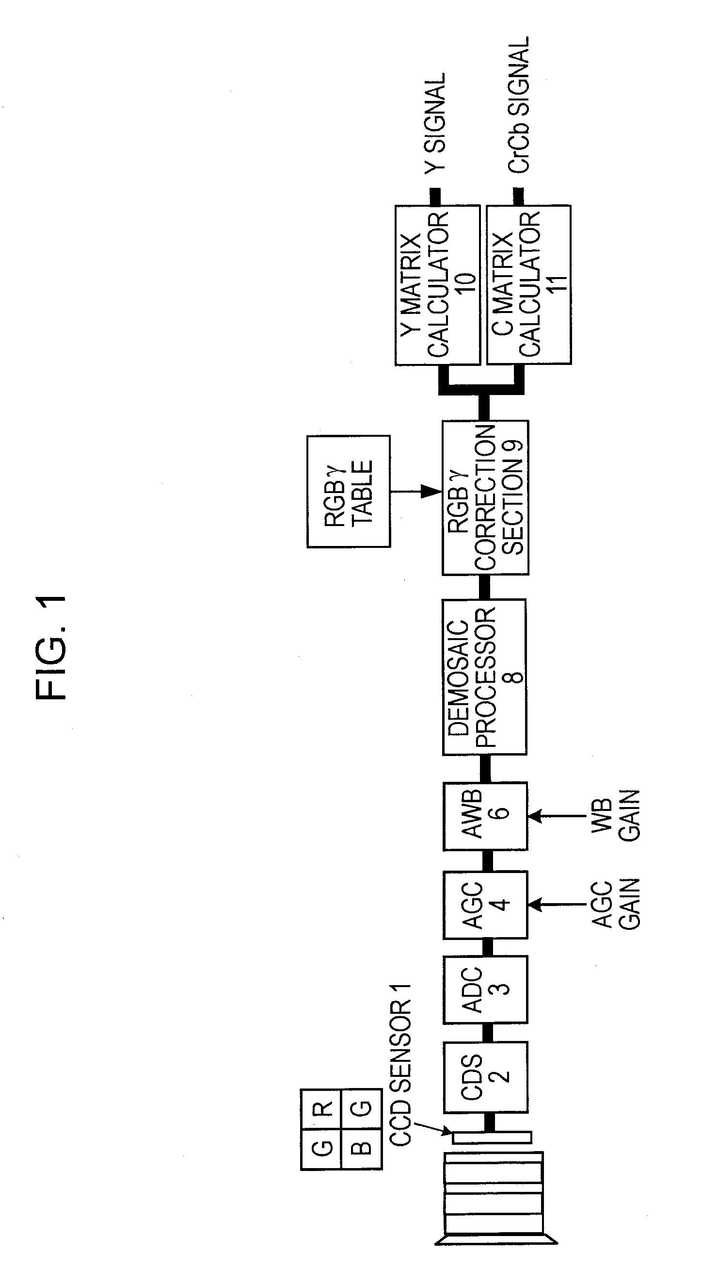
[0094]FIG. 1 shows the configuration of an image signal processing apparatus according to an embodiment of the present invention. The apparatus outputs a luminance signal and color-difference signals (Y / Cr / Cb, etc.) on the basis of an RGB image signal obtained by performing signal processing on an image obtained from a solid-state image-capturing device or the like. In the example shown in FIG. 1, function configuration for performing operation when set to ISO 100, that is, to minimum ISO sensitivity, is shown.

[0095]For a sensor 1, a solid-state image-capturing device, such as a CCD, is used. Pixels having a photoelectric conversion effect are arranged in two dimensions and, for example, a G checkered RB color coding single plate is arranged on the light-receiving side. Signal electric charge corresponding to the amount of incident light passed through each color filter is s...


PUM


Abstract

A dynamic range is widened by effectively using an output range that is originally possessed by a solid-state image-capturing device, and an image having less color hue rotation is obtained.By using the fact that the margin until the amount of saturation electric charge is reached becomes large as a result of the amount of exposure being set to be low in a high sensitivity mode, an RGB signal having a wide dynamic range containing signal components of a subject on the high-luminance side is obtained. First, γ correction close to a power γ is performed and thereafter, the signal is color-space-converted into a luminance signal and color-difference signals. A non-linear compression process is performed on the luminance signal so as to be fit into predetermined gradations, and for the color-difference signals, color rotation is reduced using a power gamma and color-difference matrix clipping is performed.

Description

TECHNICAL FIELD[0001]The present invention relates to an image signal processing apparatus for outputting a luminance signal and color-difference signals (Y / Cr / Cb, etc.) having an appropriate dynamic range on the basis of an image signal obtained from a solid-state image-capturing device and to an image signal processing method for use with the image signal processing apparatus. More particularly, the present invention relates to an image signal processing apparatus for widening a dynamic range by effectively using an output range that is primarily possessed by a solid-state image-capturing device and for obtaining an image having less color hue rotation and an image signal processing method for use with the image signal processing apparatus.BACKGROUND ART[0002]Cameras have a long history as means for recording visual information. In recent years, in place of silver-halide cameras for taking photographs by using a film and a photosensitive plate, digital cameras for digitizing an im...

Claims


Application Information

Patent Timeline
Patent Type & Authority Applications(United States)
IPC IPC(8): H04N9/68G06K9/00
CPCH04N5/20H04N5/202H04N9/67H04N9/045H04N5/243H04N23/76H04N23/843H04N9/64H04N23/10H04N23/12
Inventor WAKAGI, TORUDEGUCHI, TATSUYABABA, MAKIKO
Owner SONY CORP
Why Eureka
Try Eureka