Mobile device

a mobile device and camera technology, applied in the field of mobile devices, can solve the problems of reducing the size of the camera-shake correcting mechanism, affecting the image quality of the object, and unable to form an image at the right position,

Active Publication Date: 2009-03-12
NANCHANG O FILM OPTICAL ELECTRONICS TECH CO LTD
View PDF8 Cites 37 Cited by
  • Summary
  • Abstract
  • Description
  • Claims
  • Application Information

AI Technical Summary

Benefits of technology

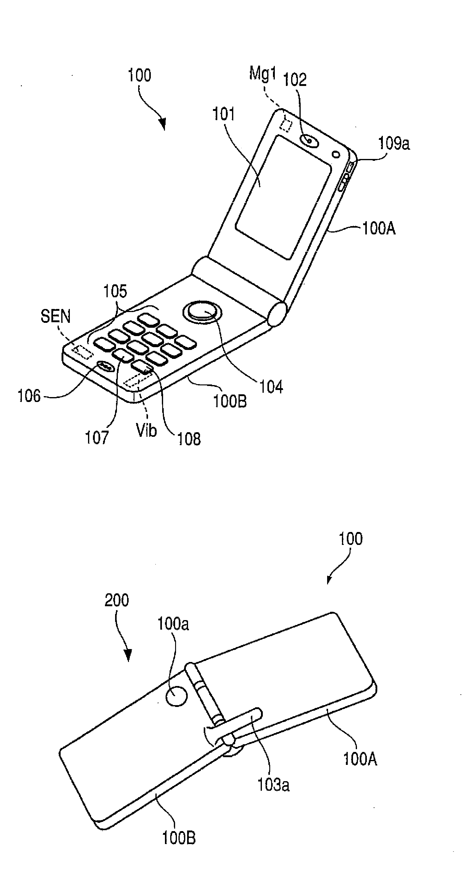
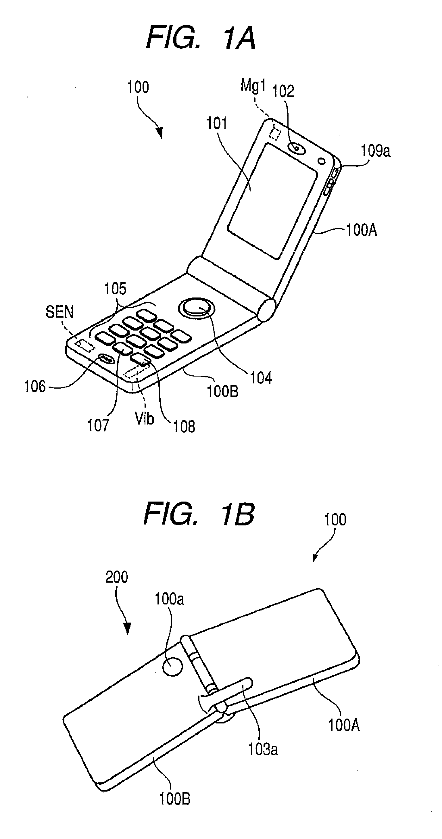
[0037]When the camera module is mounted on the portable cellular phone so that the liquid crystal display can be arranged between the camera module and the ear piece of the portable cellular phone, it is possible to ensure a distance of not less than 10 mm between the speaker, which is an example of magnetism generating element, ...

Problems solved by technology

When the size of the camera-shake correcting mechanism is forcibly reduced, problems are caused in which bearing portions of the rotary joints become fragile.
Therefore, the optical axis of the lens and that of the sensor face are shifted from each other and it becomes impossible for the light from the object to form an image at the right position.
Therefore, when the camera module is mounted at a position close to the speaker at the time o...

Method used


Image

  • Mobile device
  • Mobile device
  • Mobile device

Examples


first embodiment

[0092]Even in the sliding type shown in FIG. 6A, FIG. 6B and FIG. 6C, when the camera module 200 is arranged at the same position as that of the first embodiment, it is possible to positively operate the camera module 200.

fourth embodiment

[0093]FIG. 7A, FIG. 7B and FIG. 8 are views respectively showing the third and the fourth embodiment, the constitution of which will be explained below.

[0094]FIG. 7A and FIG. 7B are views showing an example in which the camera module 200 is arranged at a left lower position of the liquid crystal display 301 of the upper side housing 300A. FIG. 8 is a view showing an example in which the camera module 200 is arranged at a left lower position of the push buttons 305 of the lower side housing 300B.

third embodiment

[0095]In the third embodiment shown in FIG. 7A and FIG. 7B, even when the camera module 200 is arranged on the left lower side of the liquid crystal display of the upper side housing 300A, as shown in FIG. 7B, it is possible to arrange the camera module 200 at a position distant from the antenna 303, the vibrator Vib and the ear piece 302 by the distance not less than 10 mm. Therefore, this constitution can be accepted.

[0096]An electric condenser microphone is usually used for the microphone 306. Therefore, the microphone is not a magnetism generating element. Therefore, it is possible to arrange the camera module 200 at a position adjacent to the microphone 306 as shown in FIG. 8. Although it becomes a little difficult to hold the portable cellular phone at the time of photographing, even when the camera module 200 is arranged at the position shown in FIG. 8, it is possible to guarantee a positive operation of the camera module.

[0097]Finally, there is provided a portable cellular p...


PUM


Abstract

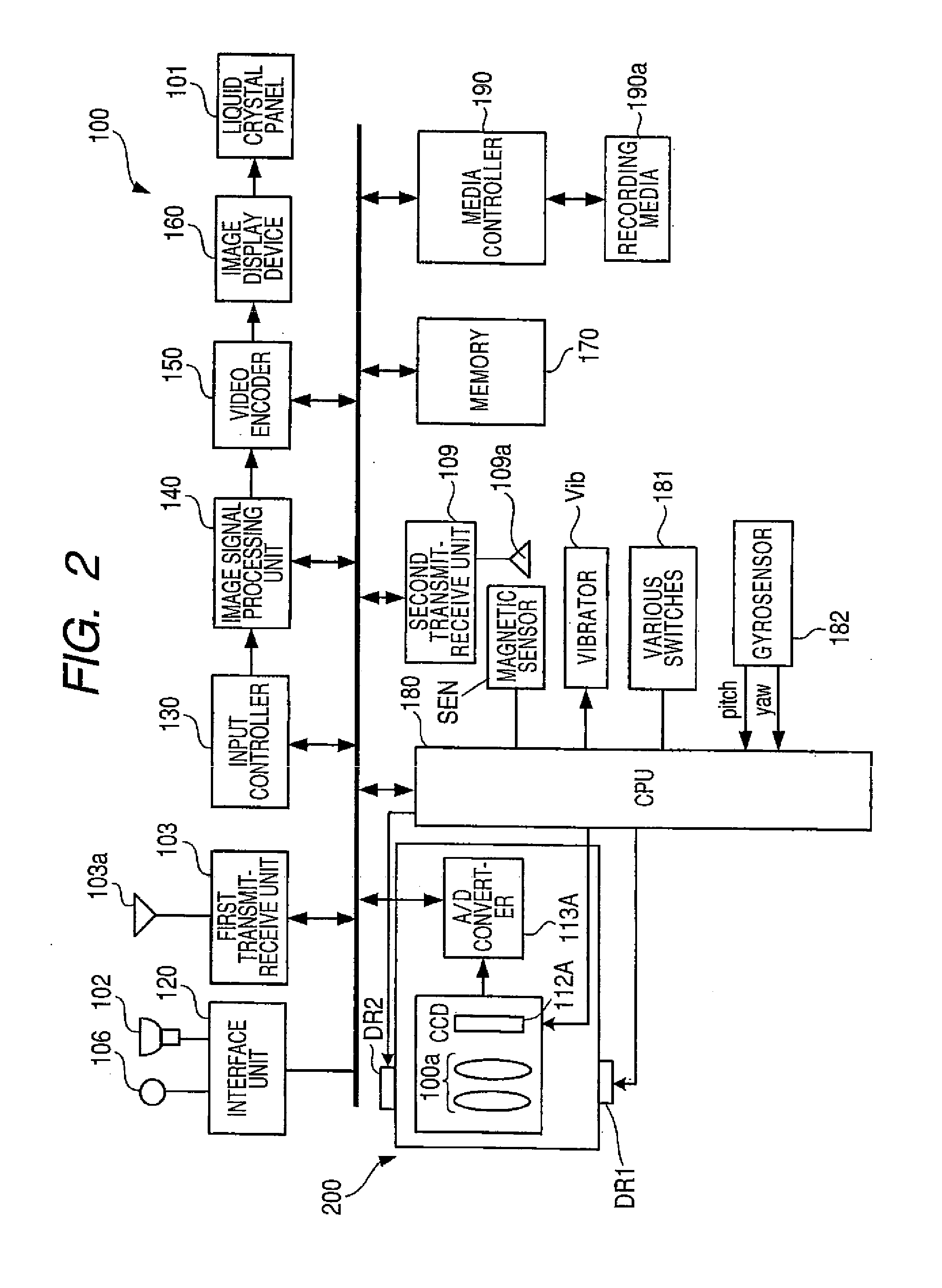
A mobile device includes a camera module and a magnetism generating part that is different from the camera module. The camera module includes: a movable portion that corrects camera shake; a magnetism detecting element that detects a position of the movable portion. when the camera module is in a photographing state, the magnetism generating part is arranged at a position distant from the magnetism detecting element by at least the distance of D mm or more, where
D=magneticforceofthemagnetismgeneratingpart[gauss].

Description

CROSS-REFERENCE TO RELATED APPLICATIONS[0001]This application is based on and claims priority under 35 USC 119 from Japanese Patent Application No. 2007-236651 filed Sep. 12, 2007; the entire contents of which are incorporated herein by reference.BACKGROUND[0002]1. Technical Field[0003]The present invention relates to a mobile device having a camera module and magnetism generating parts different from the camera module.[0004]2. Related Art[0005]Digital cameras employ various types of camera-shake correcting mechanisms for suppressing blur generated on photographed images by jigging of a user's hand. Concerning this matter, refer to Patent Documents 1 (JP Hei.7-274056 A), 2 (JP 2005-326807 A corresponding to US 2005 / 0225646 A) and 3 (JP 2612371 B).[0006]In the camera-shake correcting mechanisms described above, some of them adopt a so-called gimbal mechanism in which a holding module which holds a picture-taking lens can be freely rotated in the pitching and the yawing direction.[000...

Claims


Application Information

Patent Timeline
IPC IPC(8): H04N5/228G03B17/00
CPCH04M1/0214H04M1/0243H04N5/23248H04N5/2257H04M1/0264H04N23/57H04N23/68
Inventor YOSHIDASEKINO, SHIZUOOZAWA, KATSUJI
Owner NANCHANG O FILM OPTICAL ELECTRONICS TECH CO LTD
Why Eureka
Try Eureka