Jet burner with cooling duct in the base plate

a technology of cooling ducts and jet burners, which is applied in the direction of machines/engines, mechanical equipment, lighting and heating apparatus, etc., can solve the problems of local increase in flame temperature and thus in nox emissions, and achieve the effects of slowing down airflow, reducing raw material costs, and reducing production costs

Active Publication Date: 2016-01-21
SIEMENS ENERGY GLOBAL GMBH & CO KG
View PDF9 Cites 6 Cited by
  • Summary
  • Abstract
  • Description
  • Claims
  • Application Information

AI Technical Summary

Benefits of technology

[0022]In an alternative embodiment, the base plate is a sheet metal construction. This solution also makes it possible to reduce production costs in comparison to the variant with solid forged material, merely by virtue of substantially lower raw material costs.
[0023]In particular, but not exclusively, in the case of a sheet metal construction, it is advantageous if a circumferential wall extending beyond the cold gas side of the base plate approaches a central axis of the jet burner with increasing distance from the base plate. This wall and the—typically cylindrical—outer casing part surrounding it then form a type of diffuser, which slows the airflow provided by the compressor and advantageously increases the pressure.
[0024]

Problems solved by technology

This causes a local increase in the flame

Method used


Image

  • Jet burner with cooling duct in the base plate
  • Jet burner with cooling duct in the base plate
  • Jet burner with cooling duct in the base plate

Examples


Embodiment Construction

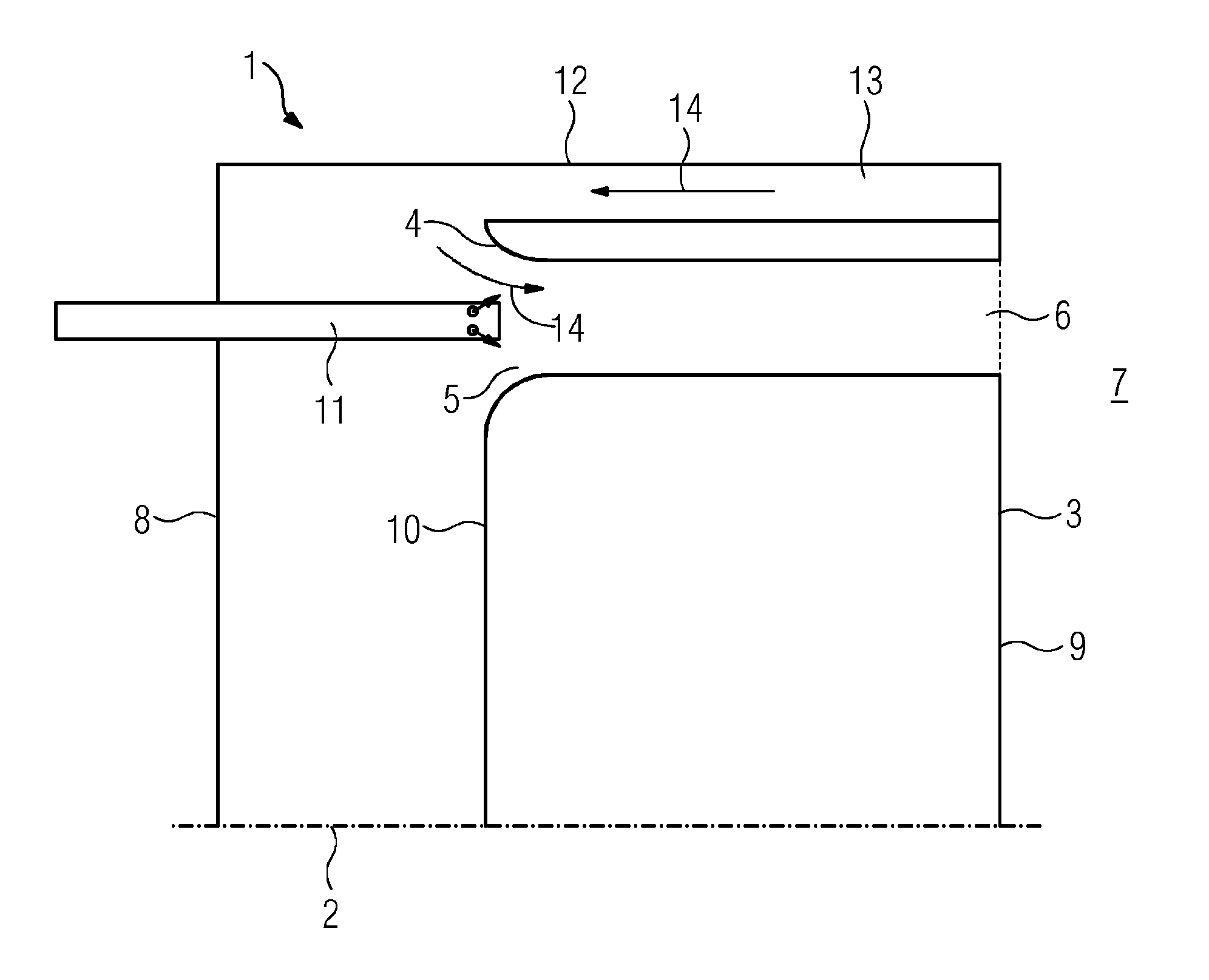
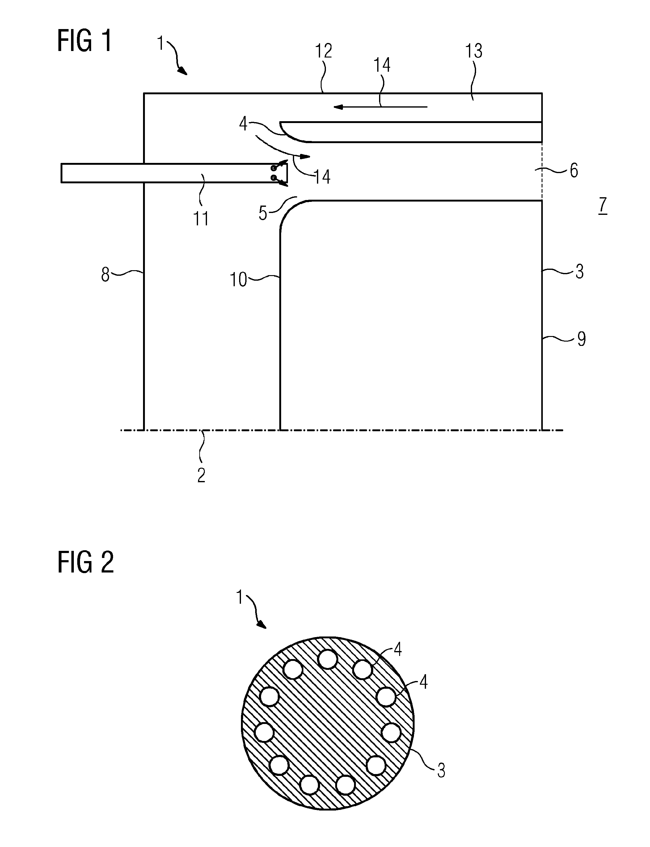
[0033]FIG. 1 shows schematically a section through a part of a jet burner 1 in the longitudinal direction, that is to say along the central axis 2 of the burner 1 according to the prior art. The burner 1 has at least one jet nozzle 4 arranged in a nozzle carrier 3. The jet nozzle 4 comprises a jet nozzle inlet 5 and the jet nozzle outlet 6. The combustion chamber 7 adjoins the jet nozzle outlet 6. In addition, the jet nozzle 4 is arranged in the nozzle carrier 3 such that the jet nozzle inlet 5 is oriented toward the rear wall 8 of the burner 1. That side of the jet burner 1 which is oriented toward the combustion chamber 7 is termed the hot gas side 9; the side oriented away from the combustion chamber 7 is termed the cold gas side 10. A fuel nozzle 11 is arranged in the region of the jet nozzle inlet 5 of the jet nozzle 4. Fuel is injected into the jet nozzle 4 through the fuel nozzle 11. The burner 1 further comprises a radially—with respect to the central axis 2 of the burner 1—...


PUM


Abstract

A jet burner has a hot-gas side, which faces toward a combustion chamber during operation, and a cold-gas side, which faces away from a combustion chamber, including a base plate on which there are arranged multiple jet nozzles, wherein the base plate has at least one cooling duct, wherein the at least one cooling duct issues into a burner stage which comprises a pilot burner arranged on the base plate.

Description

CROSS REFERENCE TO RELATED APPLICATIONS[0001]This application is the US National Stage of International Application No. PCT / EP2014 / 052410 filed 7 Feb. 2014, and claims the benefit thereof. The International Application claims the benefit of German Application No. DE 102013204307.4 filed 13 Mar. 2013. All of the applications are incorporated by reference herein in their entirety.FIELD OF INVENTION[0002]In modern gas turbine combustion systems, local hot gas temperatures exceed the currently permissible temperature limits of superalloys with thermal barrier layers, such that additional cooling is required.[0003]The invention therefore relates to the cooling of the nozzle support of a jet burner.BACKGROUND OF INVENTION[0004]Jet-stabilized combustion systems, in which the fuel is combusted in a jet flame downstream of the burner, have a simple premix zone in comparison to swirl-stabilized systems. Since the pressure difference in the burner is converted exclusively into the axial veloci...

Claims


Application Information

Patent Timeline
IPC IPC(8): F23R3/00F23R3/04F23R3/34
CPCF23R3/005F23R3/04F23R2900/03045F23R3/002F23R2900/03043F23R3/343F23R3/10F23R3/286F23R2900/03282
Inventor BECK, CHRISTIANBEZ, SIMONBUCHHOLZ, BJORNGRIEB, THOMASHASE, MATTHIASKREBS, WERNERKOSTLIN, BERTHOLDREICH, STEFANTERTILT, MARCWILKES, JAN
Owner SIEMENS ENERGY GLOBAL GMBH & CO KG
Why Eureka
Try Eureka