Spinal Interbody Device

a technology of spinal interbody and spinal cord, which is applied in the field of spinal interbody devices, can solve the problems of spinal motion limitation, spinal motion limitation, and limited rotational motion of the spinal interbody device, once implanted, and achieve the effect of motion limitation

Inactive Publication Date: 2009-03-12
LIFE SPINE INC
View PDF14 Cites 3 Cited by
  • Summary
  • Abstract
  • Description
  • Claims
  • Application Information

AI Technical Summary

Benefits of technology

[0010]A spinal interbody or intravertebral device is disclosed for fusion and non-fusion spinal applications. The spinal interbody device allows for limited motion between adjacent vertebrae to help preserve normal motion

Problems solved by technology

Rotational motion of the spinal interbody device, once implanted, may also be limited by the present configuration.
This limitation of spinal motion is particularly wi

Method used


Image

  • Spinal Interbody Device
  • Spinal Interbody Device
  • Spinal Interbody Device

Examples


Embodiment Construction

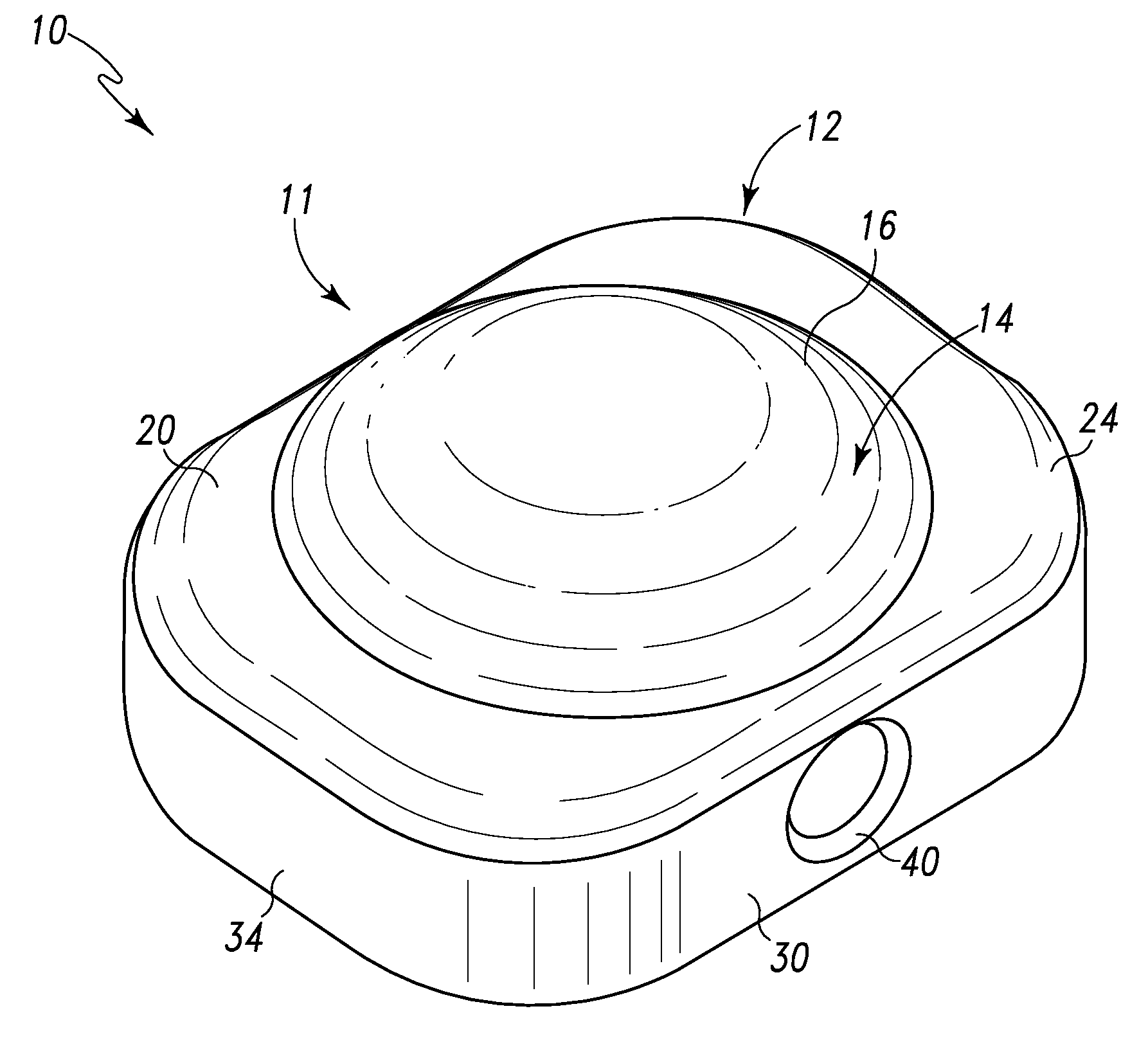
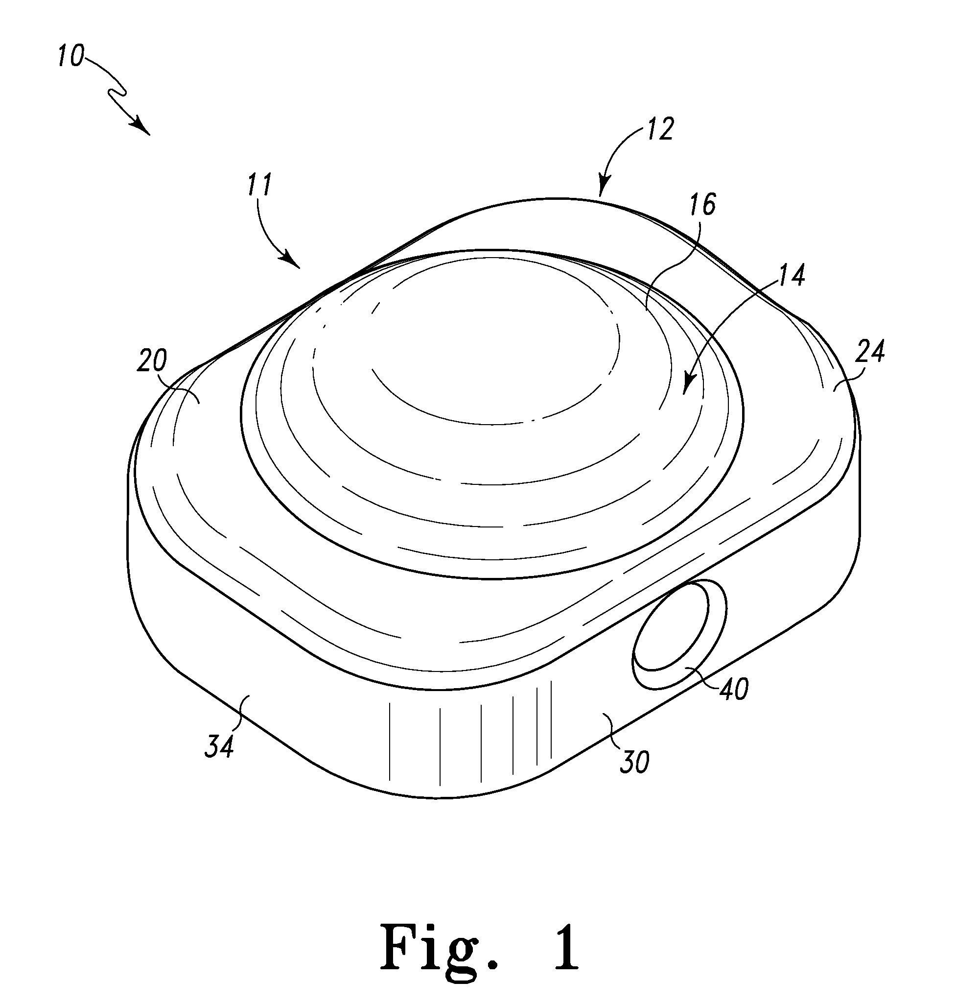
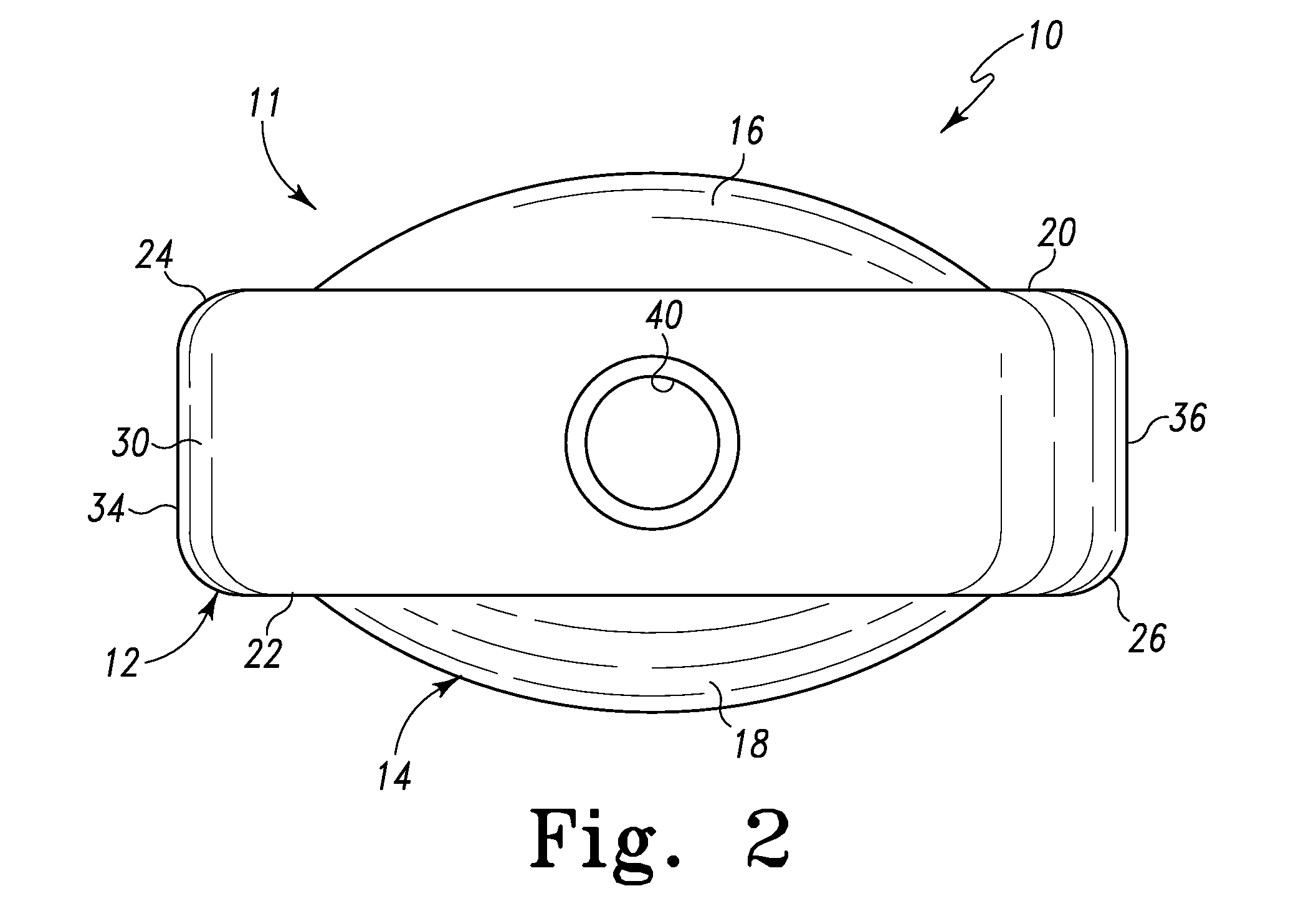
[0025]Referring to FIGS. 1-3 there is depicted an exemplary spinal interbody or intravertebral device, generally designated 10, fashioned in accordance with the present principles. The spinal interbody device 10 is characterized by a body 11 having a base, ring, band or a protrusion 12 and a ball-shaped or rounded hub, core, middle or center 14. The body 11 is sized to be received between adjacent vertebrae of the spine but to not extend beyond the periphery of the vertebra. As such, the body 11 may be fabricated in various sizes to accommodate various sizes of vertebrae and / or applications.

[0026]The base 12 may be solid (as shown) or may have one or more cavities therein. The one or more cavities may be in communication with an exterior of the body through a bore or channel in the body. Alternatively or additionally, the body may have one or more bores or channels therethrough. For instance, the body may have a single hole or bore through the center or middle of the base, or may ha...


PUM


Abstract

A spinal interbody or intravertebral device is provided for fusion and non-fusion spinal applications. The spinal interbody device allows for limited motion between adjacent vertebrae to help preserve normal motion between adjacent vertebrae (superior/inferior vertebrae) relative to the implanted spinal interbody device and limited rotational motion of the spinal interbody device, once implanted. Limitation of motion is achieved through one or more protrusions incorporated into the spinal interbody device. The protrusions preferably, but not necessarily, extend radially from a hub or ball-shaped body of the interbody device. In one form, a single protrusion extends radially about the hub of the interbody device to form a continuous band, ring or base about the hub. In this form, portions of the band may extend radially further from the hub than other portions of the band. Preferably, but not necessarily, in this form the band extends radially a greater distance from the hub in the posterior and anterior directions. In another form, a first protrusion extends radially from one side of the hub while a second protrusion extends radially from another side of the hub. Anchoring means may also be provided for attachment to upper and lower vertebrae.

Description

RELATED APPLICATIONS[0001]This patent application claims the benefit of and / or priority to U.S. Provisional Patent Application Ser. No. 60 / 993,476 filed Sep. 12, 2007, entitled “Spinal Interbody Device” the entire contents of which is specifically incorporated herein by this reference.BACKGROUND OF THE INVENTION[0002]1. Field of the Invention[0003]The present invention relates to spinal interbody devices for implantation between a pair of adjacent vertebrae in order to provide support to the adjacent vertebrae and / or promote bone fusion between the adjacent vertebrae.[0004]2. Background Information[0005]The disc between vertebrae of a human spine is sometimes damaged due to disease or injury, or may simply deteriorate due to age, disease, injury or congenital defect. With others, the vertebrae may become compressed or otherwise damaged. In these and other cases the vertebrae can become too closely spaced anteriorly which causes an undesired abnormal curvature of the spine with respe...

Claims


Application Information

Patent Timeline
IPC IPC(8): A61F2/44
CPCA61B17/0642A61B17/842A61F2/442A61F2/4455A61F2/4611A61F2002/30014A61F2250/0018A61F2002/30242A61F2002/30462A61F2002/30563A61F2002/30772A61F2220/0075A61F2230/0071A61F2002/30069
Inventor BUTLER, MICHAEL S.HARTSELL, BRIAN D.
Owner LIFE SPINE INC
Why Eureka
Try Eureka