Vehicle dual hinge rear door articulating and sliding system

a rear door and hinge technology, applied in the direction of doors, roofs, transportation items, etc., can solve the problems of affecting the safety of passengers, so as to prevent the sliding movement of the vehicle door and the effect of preventing the sliding movement of the compartment closur

Inactive Publication Date: 2009-03-19
FORD GLOBAL TECH LLC
View PDF82 Cites 60 Cited by
  • Summary
  • Abstract
  • Description
  • Claims
  • Application Information

AI Technical Summary

Benefits of technology

[0012]In an exemplary embodiment, the vehicle rear door articulating and sliding mechanism may include a dual hinge connected to the rear end of the door and for connection to a C-pillar of a vehicle body to allow the rear end (trailing edge) of the rear door to articulate open, through an arc representing approximately 110° (or between approximately 75° to 135°) relative to a vehicle A-B line, thereby drawing the front end (leading edge) away from the point of contact (interface) to the front door. The articulation allows the complete door assembly to be rotated clear of the door opening prior to commencement of a sliding motion in a rearward direction. A check may prevent rotation of the hinges beyond 110° and place the door in a position to slide. The sliding motion may be facilitated by means of a linear guideway, positioned horizontally, or at a preferred linear movement angle, which may involve a bearing pack and guide rails, conventional polymer wheels within a guiding track, or any other means of conveying the door in a fore-aft direction. The track for sliding may be packaged within the door, so that no external track on body is required. Stability of the door in both a fore and aft and in and out direction may be maintained through an upper guide packaged within the roof rail or cantrail and / or a lower guide mounted to the vehicle rocker. The door on closing may be guided using a track mounted on the vehicle roof and / or a front bottom surface of the door, for which a front striker may slide through this to engage a latch mounted at the rear of the track.
[0013]For the vehicle rear door articulating and sliding mechanism described above, the slide block may be pivotally mounted to the opposite end of the hinge arm. The opposite end of the hinge arm may further include a fixedly mounted curved check engageable with a complementary curved detent provided on the vehicle rear door for preventing sliding movement of the vehicle rear door. The curved check may be disengageable from the complementary curved detent for allowing articulating movement of the vehicle rear door. In a particular embodiment, the curved check may include a roller engageable with the complementary curved detent. In a particular embodiment, a surface of the hinge arm may be contiguously engageable with a surface of the slide block to limit pivotal movement of the hinge arm relative to the slide block. The vehicle rear door articulating and sliding mechanism may further include a guide assembly including a vehicle roof mounted guide track and a guide arm mounted to the vehicle rear door and having a follower slidable relative to the vehicle roof mounted guide track for facilitating guided movement of the vehicle rear door. Alternatively, the guide assembly may include a vehicle floor mounted guide track and a guide arm mounted to the vehicle rear door and having a follower slidable relative to the vehicle floor mounted guide track for facilitating guided movement of the vehicle rear door. The vehicle rear door articulating and sliding mechanism may further include a tie-rod connected to an upper and lower hinge arm for thereby providing rigidity for simultaneous operation of upper and lower hinge assemblies.
[0014]The invention also provides a vehicle door articulating and sliding mechanism including one or more articulating hinge assemblies including one or more hinge arms pivotally mounted to a vehicle body structure at one end thereof, and a vehicle door pivotally and slidably mounted to the hinge arm at an opposite end of the hinge arm. The mechanism may further include one or more guide tracks mounted to the vehicle door, and one or more slide blocks pivotally mounted to the hinge arm and slidably attached to the guide track. The hinge arm may be disposed at first and second angular positions relative to the guide track when the vehicle door is respectively disposed in closed and opened positions, and the slide block may be disposed at first and second positions along a length of the guide track when the vehicle door is respectively disposed in the closed and opened positions. The vehicle door articulating and sliding mechanism thus provides articulating movement of the vehicle door during initial opening thereof and further provides sliding movement of the vehicle door relative to the vehicle body during continued opening thereof.
[0015]For the vehicle door articulating and sliding mechanism described above, the mechanism may provide articulating movement of the vehicle door, independent of a vehicle adjacent door. The slide block may be pivotally mounted to the opposite end of the hinge arm, and the opposite end of the hinge arm may further include a fixedly mounted curved check engageable with a complementary curved detent provided on the vehicle door for preventing sliding movement of the vehicle door. The curved check may be disengageable from the complementary curved detent for allowing articulating movement of the vehicle door. In a particular embodiment, the curved check may include a roller engageable with the complementary curved detent. In a particular embodiment, a surface of the hinge arm may be contiguously engageable with a surface of the slide block to limit pivotal movement of the hinge arm relative to the slide block. The vehicle door articulating and sliding mechanism may further include a guide assembly including a vehicle roof mounted guide track and a guide arm mounted to the vehicle door and having a follower slidable relative to the vehicle roof mounted guide track for facilitating guided movement of the vehicle door. Alternatively, the guide assembly may include a vehicle floor mounted guide track and a guide arm mounted to the vehicle door and having a follower slidable relative to the vehicle floor mounted guide track for facilitating guided movement of the vehicle door. In a particular embodiment, the vehicle door articulating and sliding mechanism may further include a tie-rod connected to an upper and lower hinge arm for thereby providing rigidity for simultaneous operation of upper and lower hinge assemblies.
[0017]For the vehicle compartment closure articulating and sliding mechanism described above, the slide block may be pivotally mounted to the opposite end of the hinge arm, and the opposite end of the hinge arm may further include a fixedly mounted curved check engageable with a complementary curved detent provided on the compartment closure for preventing sliding movement of the compartment closure. The curved check may be disengageable from the complementary curved detent for allowing articulating movement of the compartment closure. In a particular embodiment, the curved check may include a roller engageable with the complementary curved detent. A surface of the hinge arm may be contiguously engageable with a surface of the slide block to limit pivotal movement of the hinge arm relative to the slide block. The mechanism may further include a tie-rod connected to parallel hinge arms for thereby providing rigidity for simultaneous operation of parallel hinge assemblies.

Problems solved by technology

Due to the large size of a typical pick-up truck, driver / passenger ingress / egress can become particularly restrictive, if not impossible, if a vehicle is parked adjacent to the truck and is sufficiently close to prevent a person from boarding or loading to enter the area between the front and rear doors (when open), invariably known as parking lot entrapment.
Referring to FIGS. 4-6, hinge / arm assembly (30, 32) is also relatively complex in design, and requires substantial modification of the vehicle structure for adequate operation thereof.

Method used


Image

  • Vehicle dual hinge rear door articulating and sliding system
  • Vehicle dual hinge rear door articulating and sliding system
  • Vehicle dual hinge rear door articulating and sliding system

Examples


Embodiment Construction

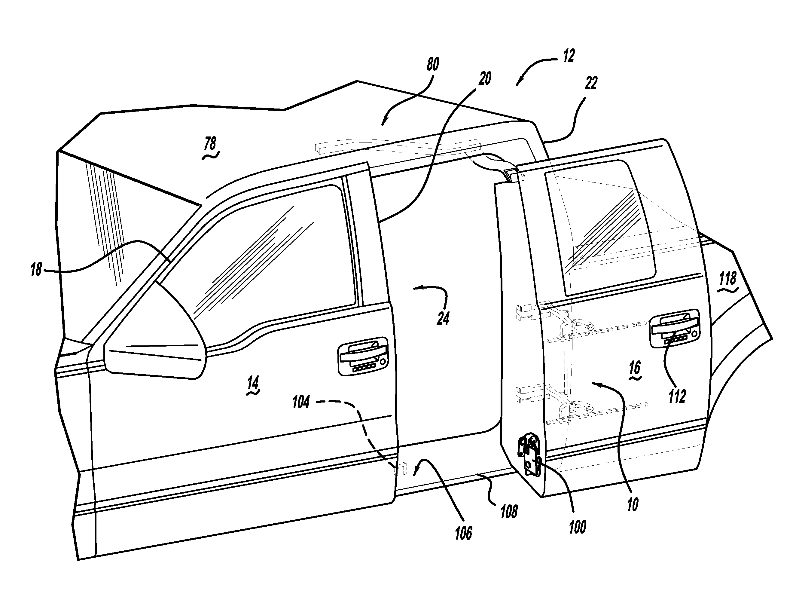
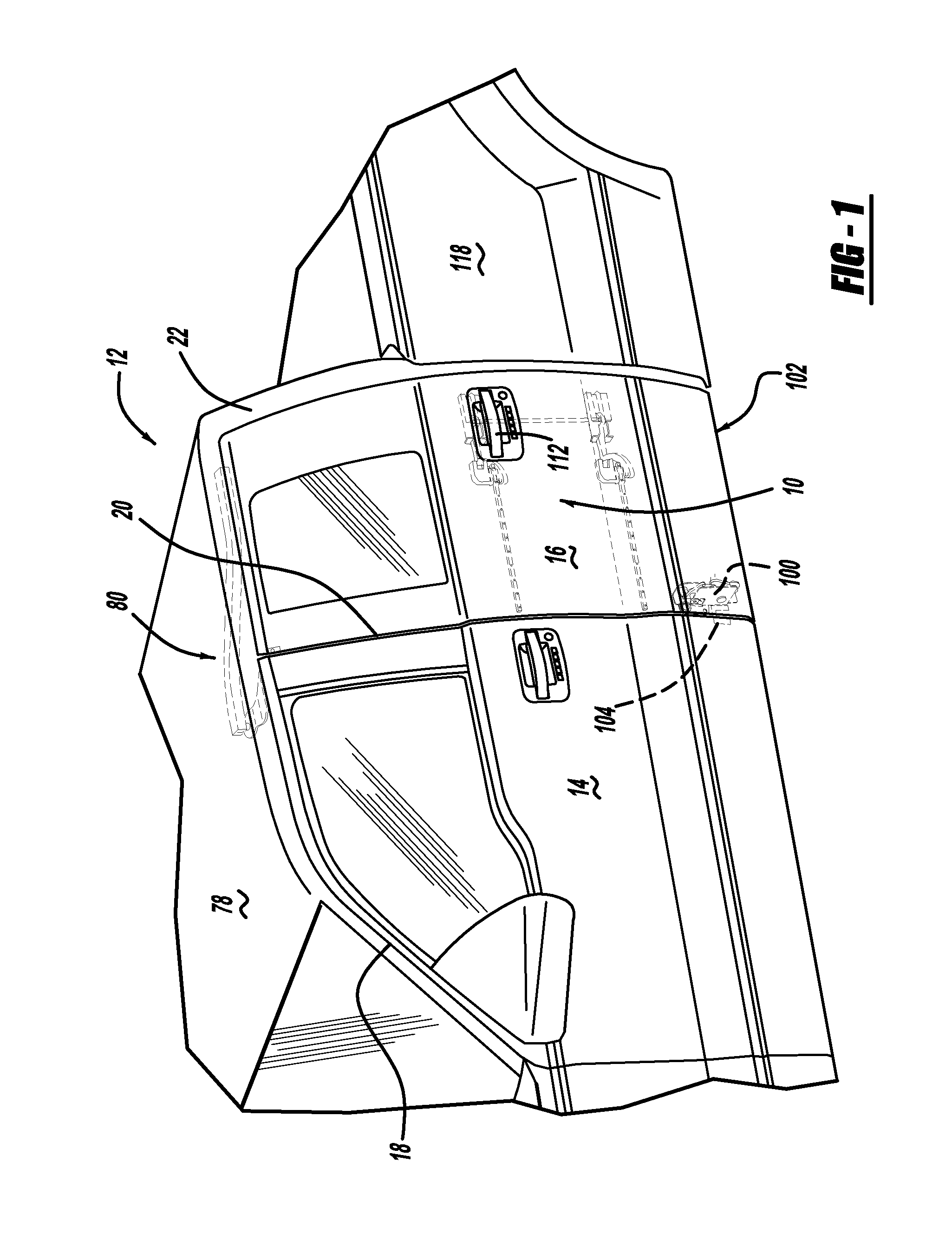
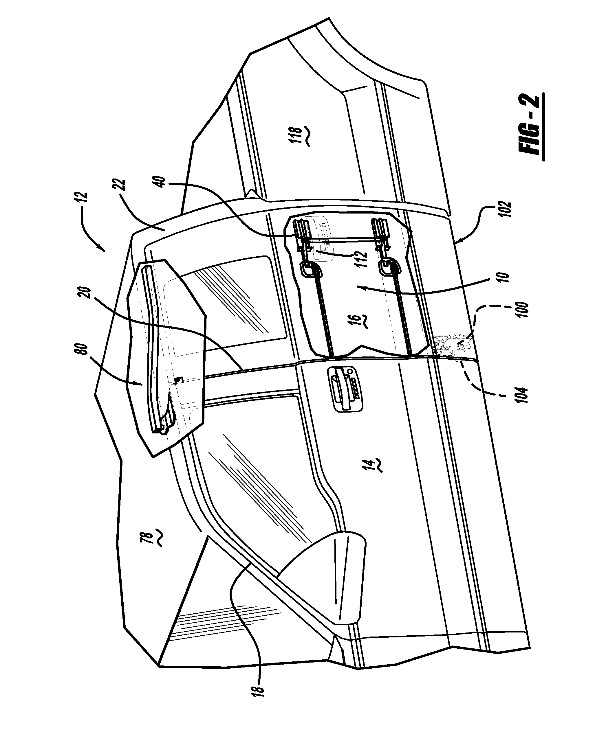
[0037]Referring now to the drawings wherein like reference numerals designate corresponding parts throughout the several views, FIGS. 1-16B illustrate a mechanism for vehicle rear door articulation and sliding according to the present invention, generally designated “rear door articulating and sliding mechanism 10.”

[0038]Referring to FIGS. 1-3, rear door articulating and sliding mechanism 10 may generally be mounted onto a vehicle 12 including front and rear doors 14, 16. In the exemplary embodiment illustrated, vehicle 12 may be a pickup truck including A, B and C pillars 18, 20, 22. As shown in FIGS. 4 and 5, and described in greater detail below, in order to facilitate ingress and egress into and from compartment 24 of vehicle 12, rear door articulating and sliding mechanism 10 may allow for complete opening of rear door 16, with front door 14 being fully opened or closed.

[0039]The various sub-components of rear door articulating and sliding mechanism 10 will now be described in ...


PUM


Abstract

A vehicle rear door articulating and sliding mechanism including an articulating hinge assembly having a hinge arm pivotally mounted to a vehicle C-pillar at one end thereof, and a vehicle rear door pivotally and slidably mounted to the hinge arm at an opposite end of the hinge arm. A guide track may be mounted to the rear door, and a slide block may be pivotally mounted to the hinge arm and slidably attached to the guide track. The hinge arm may be disposed at first and second angular positions relative to the guide track when the rear door is respectively disposed in closed and opened positions, and the slide block may be disposed at first and second positions along a length of the guide track when the rear door is respectively disposed in the closed and opened positions, to thus provide articulating and sliding movement of the rear door.

Description

RELATED APPLICATIONS[0001]This application claims benefit of priority of Provisional Application Ser. No. 60 / 972,555 filed Sep. 14, 2007, hereby incorporated by reference in its entirety.BACKGROUND OF INVENTION[0002]a. Field of Invention[0003]The invention relates generally to vehicle door movement control devices, and, more particularly, to a mechanism for vehicle rear door articulation and sliding, for example, in a pickup truck, with the mechanism permitting opening and closing of a rear door with or without a front door being opened.[0004]b. Description of Related Art[0005]As is known in the art, automobile designs are governed by a variety of ergonomic and operational factors. For doors and other such components, the design is generally based on ergonomic factors such as exterior appearance, and the location and visibility of hinges, latches and adjacent components, and operational factors such as the ingress / egress opening provided, the maximum clearance required for opening / c...

Claims


Application Information

Patent Timeline
Patent Type & Authority Applications(United States)
IPC IPC(8): B60J5/12B60J9/02
CPCE05Y2900/531E05D15/1081B60J5/06B60J5/0479E05Y2900/516
Inventor ELLIOTT, ADRIAN N. A.JOHNSON, JUSTIN T.FALENSKI, JASONBLUST, CRAIG
Owner FORD GLOBAL TECH LLC
Why Eureka
Try Eureka