Outward turning motor rotor for a ceiling fan

a technology for ceiling fans and motor rotors, which is applied in the direction of magnetic circuit rotating parts, dynamo-electric machines, and magnetic circuit shape/form/construction, etc., to achieve the effect of lowering noise, shock absorption, and lowering the magnetic field strength of the opposite end of each permanent magn

Inactive Publication Date: 2009-03-19
YONG SHIN T ELECTRIC MACHINE
View PDF4 Cites 11 Cited by
  • Summary
  • Abstract
  • Description
  • Claims
  • Application Information

AI Technical Summary

Benefits of technology

[0005]This invention is devised to offer an outward turning motor rotor for a ceiling fan, having effects of shock absorption and lowering noises. The outward turning motor rotor includes a stator and a rotor positioned around the outer circumference of the stator. The rotor consists of a circular-case base having its circumference provided with a circumferential wall formed with an accommodating space in the interior. A plurality of permanent magnets are equidistantly and annularly secured on the inner circumferential wall of the base, and each permanent magnet has one side facing to the stator contracted gradually from an intermediate portion toward a left and a right end, letting the opposite ends of each permanent magnet respectively form a comparatively thin pole portion. Thus, magnetic field strength of the opposite ends of each permanent magnet can be lowered, and a distance between the opposite pole portions of the permanent magnet and the stator can be lengthened. By so designing, when the rotor carries out change-over motion, a comparatively small magnetic force produced by the pole portions of the permanent magnets can stabilize vibration produced during performing change-over motion, greatly lowering noises caused by rotation of the rotor.

Problems solved by technology

However, even volumes of the permanent magnets 2 will produce an integrally even magnetic force; therefore, when carrying out change-over rotating, the rotor will be affected by an attractive force of the permanent magnets 2 to produce a change-over shifting force and cause vibration.

Method used


Image

  • Outward turning motor rotor for a ceiling fan
  • Outward turning motor rotor for a ceiling fan
  • Outward turning motor rotor for a ceiling fan

Examples


Embodiment Construction

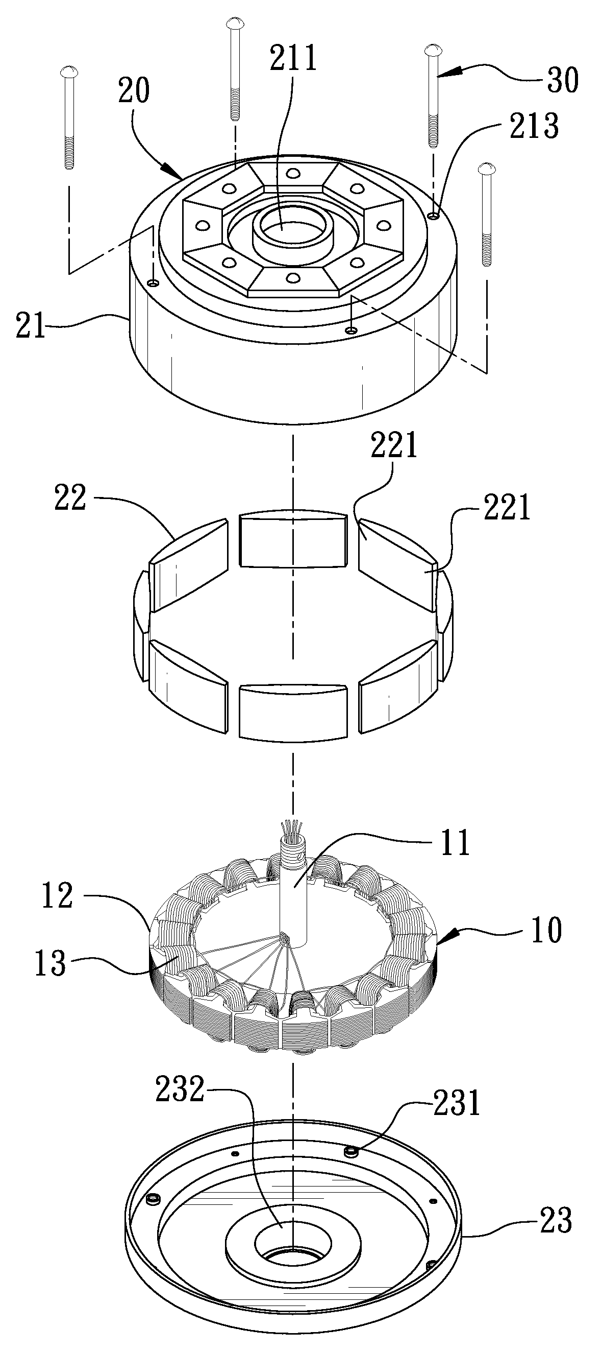
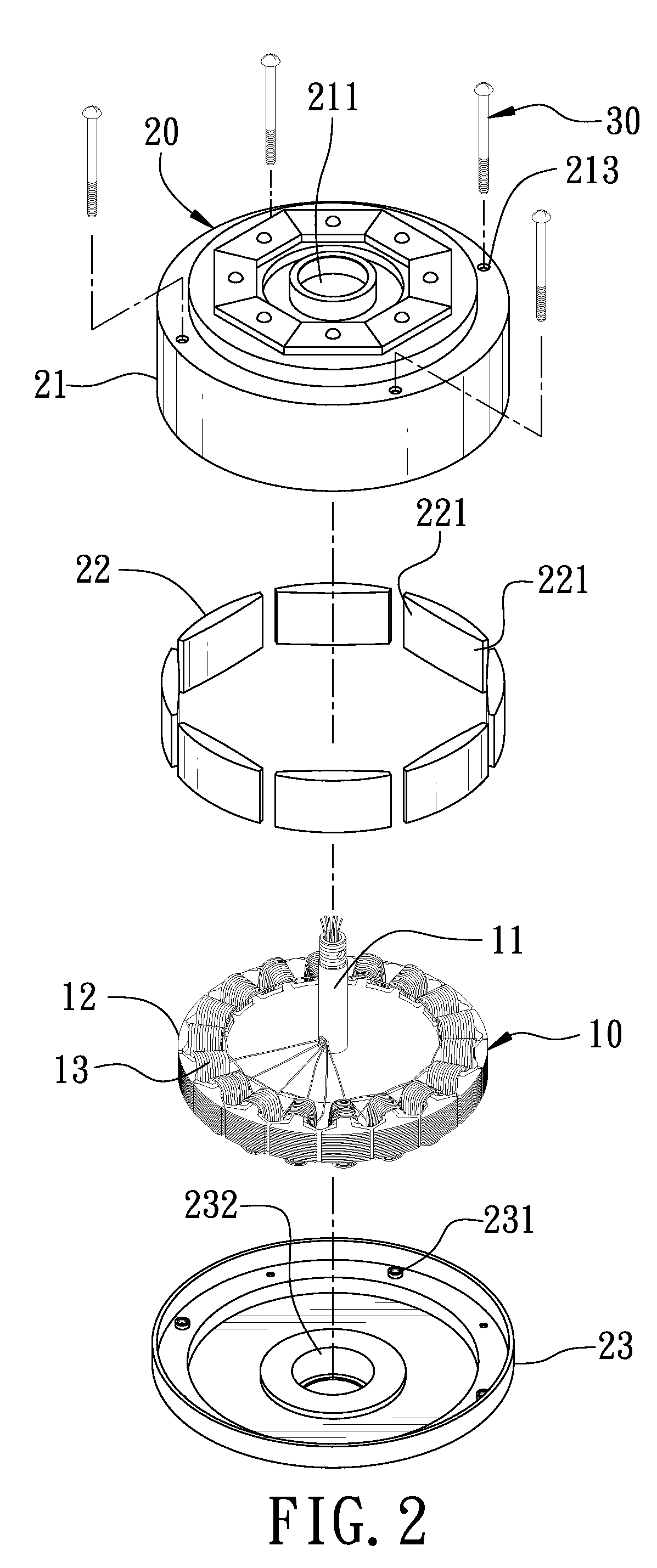
[0013]A first preferred embodiment of an outward turning motor rotor for a ceiling fan in the present invention, as shown in FIG. 2, includes a stator 10 and a rotor 20 combined together.

[0014]The stator 10 consists of a spindle 11 and an electro-magnet 12. The spindle 11 is inserted through the center of the electro-magnet 12, which is annularly positioned around the spindle 11 and orderly wound thereon with a plurality of coil sets 13.

[0015]The rotor 20 is positioned around the outer circumference of the stator 10 and separated from the stator 10 for a proper distance. The rotor 20 is composed of a base 21, a plurality of permanent magnets 22 and a cover 23.

[0016]The base 21, referring to FIG. 3, is a circular casing having its center bored with a shaft hole 211 matching with the spindle 11 of the stator 10. The base 21 has its circumference disposed with a circumferential wall formed in the interior with an accommodating space 212 having an opening facing upward. The base 21 furt...


PUM


Abstract

An outward turning motor rotor for a ceiling fan includes a stator and a rotor positioned around the outer circumference of the stator. The rotor contains a circular-case base having its circumference disposed with a circumferential wall having plural permanent magnets equidistantly and annularly secured thereon. Each permanent magnet has one side facing the stator tapered gradually from an intermediate portion toward a left end and a right end, letting the opposite ends of each permanent magnet respectively formed with a comparatively thin pole portion and lengthening a distance between the pole portions of each permanent magnet and the stator. In change-over motion, a comparatively small magnetic force produced by the pole portions of the rotor will stabilize vibration produced, greatly lowering noises caused by rotation of the rotor.

Description

BACKGROUND OF THE INVENTION[0001]1. Field of the Invention[0002]This invention relates to an outward turning motor rotor for a ceiling fan, particularly to one having effects of shock absorption and lowering noises.[0003]2. Description of the Prior Art[0004]A conventional ceiling fan motor rotor is installed around the outer circumference of a stator (not shown) and separated from the stator for a proper distance. The conventional ceiling fan motor rotor, as shown in FIG. 1, includes a circular-case base 1 and lots of permanent magnets 2 equidistantly and annularly secured on the inner circumferential wall of the base 1 and integrally curved into an arc-shaped plate with a preset thickness. The rotor is actuated to carry out change-over turning incessantly by action of mutual attraction and mutual repulsion between different magnetic poles produced by adjacent permanent magnets and the stator. However, even volumes of the permanent magnets 2 will produce an integrally even magnetic ...

Claims


Application Information

Patent Timeline
Patent Type & Authority Applications(United States)
IPC IPC(8): H02K1/28H02K1/27
CPCH02K1/2786H02K1/2791
Inventor LI, MEI-HAN
Owner YONG SHIN T ELECTRIC MACHINE
Why Eureka
Try Eureka