Versatile apparatus and method for electronic devices
Inactive Publication Date: 2009-03-19
PURE ENERGY SOLUTIONS INC
View PDF27 Cites 343 Cited by
Summary
Abstract
Description
Claims
Application Information
AI Technical Summary
This helps you quickly interpret patents by identifying the three key elements:
Problems solved by technology
Method used
Benefits of technology
Problems solved by technology
Manufacturers, however, generally make their own model of electronic device and do not make their power cord unit compatible with the electronic devices of other manufacturers, or with other types of electronic devices.
As a result, a battery connector made by one manufacturer will typically not fit into the battery power receptacle made by another manufacturer.
Further, a battery connector made for one type of device typically will not fit into the battery power receptacle made for another type of device.
This may be troublesome for the consumer because he o
Method used
Image
Click on the blue label to locate the original text in one second.
Reading with bidirectional positioning of images and text.
Examples
Embodiment Construction
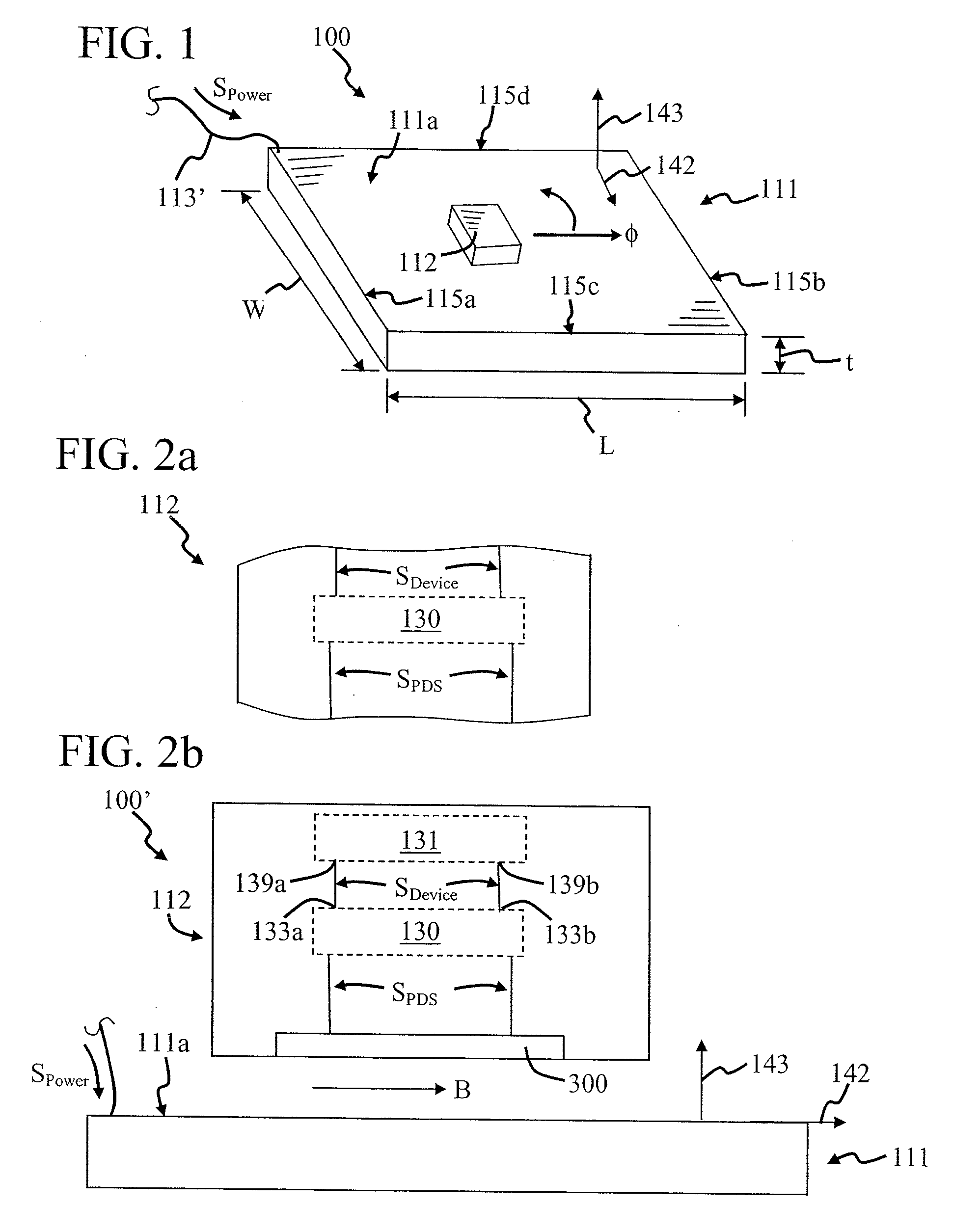
[0093]FIG. 1 is a perspective view of a power delivery system 100, in accordance with the invention. System 100 has many different embodiments that provide the features discussed herein and others. Several embodiments are discussed in co-pending U.S. patent application Ser. No. 11 / 670,842 filed on Feb. 2, 2007 and co-pending U.S. patent application Ser. No. 11 / 672,010 filed Feb. 6, 2007. In FIG. 1, system 100 includes a power delivery support structure 111 having a power delivery surface 111a which is used to provide power to an electronic device 112. Support structure 111 is connected through a power cord unit 113′ to a power source (not shown) which provides a power signal SPower to it The power source can be of many different types, such as an electrical outlet, battery, vehicle cigarette lighter system, direct connection to an electrical generator device, and solar power system, some of which are discussed in more detail below with FIGS. 5a-5c and 6a-6c. Power delivery surface 1...
PUM
Abstract
An electronic system which includes a power delivery surface that delivers electrical power to an electrical or electronic device. The power delivery surface may be powered by any electrical power source, including, but not limited to: wall electrical outlet, solar power system, battery, vehicle cigarette lighter system, direct connection to electrical generator device, and any other electrical power source. The power delivery surface delivers power to the electronic device wirelessly. The power delivery surface may deliver power via a plurality of contacts on the electrical device conducting electricity from the power delivery surface, conductively coupling the electronic device to the power delivery surface, inductively coupling the electronic device to the power delivery surface, optically coupling the electronic device to the power delivery surface, and acoustically coupling the electronic device to the power delivery surface as well as any other electrical power delivery mechanism.
Description
CROSS-REFERENCES TO RELATED APPLICATIONS[0001]This application claims the benefit of U.S. Provisional Application No. 60 / 778,761, filed Mar. 3, 2007, U.S. Provisional Application No. 60 / 781,456, filed Mar. 10, 2007, and U.S. Provisional Application No. 60 / 797,140, filed May 3, 2006, all of which are incorporated herein by reference, and it is a continuation-in-part of U.S. patent application Ser. No. 11 / 670,842, filed Feb. 2, 2007, and U.S. patent application Ser. No. 11 / 672,010, filed on Feb. 6, 2007, which additionally claims the benefit of U.S. Provisional Application No. 60 / 776,332, filed Feb. 24, 2006, which are a divisional patent application and a continuation-in-part patent application, respectively, from U.S. patent application Ser. No. 10 / 732,103, filed on Dec. 10, 2003, which claims the benefit of U.S. Provisional Application Nos. 60 / 432,072, filed Dec. 10, 2002, U.S. Provisional Application No. 60 / 441,794, filed Jan. 22, 2003, and U.S. Provisional No. 60 / 444,826, filed F...
Claims
Application Information
Patent Timeline
Application Date:The date an application was filed.
Publication Date:The date a patent or application was officially published.
First Publication Date:The earliest publication date of a patent with the same application number.
Issue Date:Publication date of the patent grant document.
PCT Entry Date:The Entry date of PCT National Phase.
Estimated Expiry Date:The statutory expiry date of a patent right according to the Patent Law, and it is the longest term of protection that the patent right can achieve without the termination of the patent right due to other reasons(Term extension factor has been taken into account ).
Invalid Date:Actual expiry date is based on effective date or publication date of legal transaction data of invalid patent.