Chassis for an illuminating unit, and an illuminating unit, a display device and a television receiver incorporating the chassis

a technology for illuminating units and chassis, which is applied in the direction of lighting and heating equipment, instruments, transportation and packaging, etc., can solve the problems of optical sheets subjected to their own weight at the peripheries, peripheries of through-holes or positioning pieces suffering wrinkles or deformations, and it is extremely difficult to narrow or eliminate the gap, realistically

Active Publication Date: 2009-03-19
SHARP KK
View PDF5 Cites 13 Cited by
  • Summary
  • Abstract
  • Description
  • Claims
  • Application Information

AI Technical Summary

Benefits of technology

[0015]In order to overcome the problems described above, preferred embodiments of the present invention provide a chassis for an illuminating unit, and an illuminating unit, a display device and a television receiver incorporating the chassis, and the chassis is such that optical sheets are support

Problems solved by technology

However, with the above-described structures, if the display device is used in an upright position, the optical sheets are subjected to their own weight at the peripheries of the through-holes or the positioning pieces.
As a result, there is a possibility that the peripheries of the through-holes or the positioning pieces suffer wrinkles or deformed portions.
Accordingly, it is extremely difficult to narrow or eliminate the gap, realistically.
However, such structures have the following problems.
As a result, the four sides of the o

Method used


Image

  • Chassis for an illuminating unit, and an illuminating unit, a display device and a television receiver incorporating the chassis
  • Chassis for an illuminating unit, and an illuminating unit, a display device and a television receiver incorporating the chassis
  • Chassis for an illuminating unit, and an illuminating unit, a display device and a television receiver incorporating the chassis

Examples


Embodiment Construction

[0032]A detailed description according to preferred embodiments of the present invention will now be provided with reference to the accompanying drawings. Here, the preferred embodiments preferably applied to an illuminating unit to be incorporated into a display device including a translucent liquid crystal display panel are described.

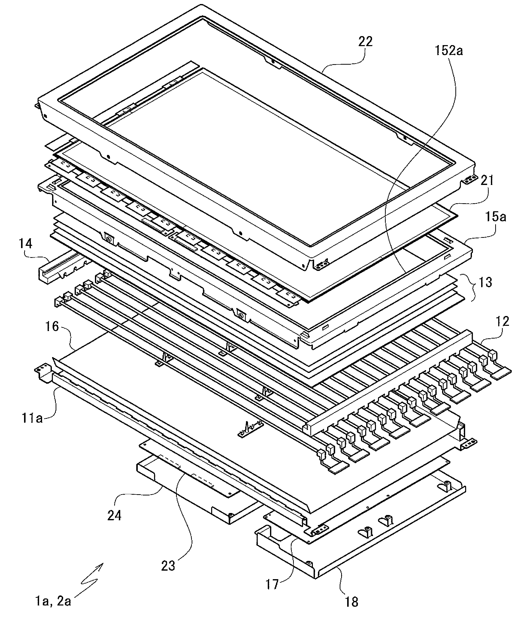
[0033]FIG. 1 is an exploded perspective view schematically illustrating a structure for assembling a translucent liquid crystal display device which incorporates a chassis for an illuminating unit or an illuminating unit for a display device according to a preferred embodiment of the present invention.

[0034]Incidentally, in FIG. 1, the illuminating unit for a display device and the display device are illustrated so that their front surfaces face toward the top of FIG. 1, and their back surfaces face toward the bottom of FIG. 1, based on which descriptions will be provided.

[0035]First, a brief description of an illuminating unit 1a for a display device...


PUM


Abstract

A chassis for an illuminating unit, and an illuminating unit, a display device and a television receiver incorporating the chassis are provided, in which optical sheets are supported in a state where their own weight and an external force are not concentrated at a certain portion thereof, preventing occurrence of wrinkles or deformed portions and falling-off of the optical sheets. A backlight chassis includes stand walls on the sides thereof on which optical sheets are to be placed, and locking pieces protruding from the stand wall on at least one of the sides, the side being a lower side in a normal state in use, and the locking pieces being arranged to lock a lower side of the optical sheets.

Description

BACKGROUND OF THE INVENTION[0001]1. Field of the Invention[0002]The present invention relates to a chassis for an illuminating unit, and an illuminating unit, a display device and a television receiver incorporating the chassis, and specifically relates to a chassis for an illuminating unit preferably applied to a display device or a television receiver having a translucent liquid crystal display panel, and an illuminating unit, a display device and a television receiver incorporating the chassis.[0003]2. Description of the Related Art[0004]Among flat-screen display devices, for example, a liquid crystal display device and other devices including a translucent liquid crystal display panel generally includes an illuminating unit placed behind the liquid crystal display panel. The illuminating unit includes a light source and optical sheets, controls the properties of light emitted from the light source using the optical sheets, and projects the light toward a back surface of the liqu...

Claims


Application Information

Patent Timeline
IPC IPC(8): F21V17/00
CPCG02F1/133308G02F1/133604G02F2201/54G02F1/133608G02F2001/133317G02F1/133606G02F1/133317
Inventor TAKATA, YOSHIKI
Owner SHARP KK
Why Eureka
Try Eureka