
Image forming apparatus

a technology of image forming and forming sleeves, which is applied in the direction of electrographic process apparatus, instruments, optics, etc., can solve the problems of poor image formation and deterioration of the durability of the gears of the driving train, and achieve the stability of the sd gap and reduce the driving load torque of the developing sleeve, and achieve high image quality and durability. , the effect of high image quality

Active Publication Date: 2009-03-19
CANON KK
View PDF17 Cites 4 Cited by
  • Summary
  • Abstract
  • Description
  • Claims
  • Application Information

AI Technical Summary

Benefits of technology

[0016]The present invention provides an image forming apparatus which can achieve stability of an SD gap and reduction of the driving load torque of a developing sleeve and cope with both high image quality and durability.

Problems solved by technology

When the SD gap Gsd is varied, poor image formation such as inconsistencies in density in an image can be caused.
The vibration of the development device 3 at transmission of the driving force can deteriorate the durability of the gears of the driving train.

Method used


Image

  • Image forming apparatus
  • Image forming apparatus
  • Image forming apparatus

Examples


embodiment

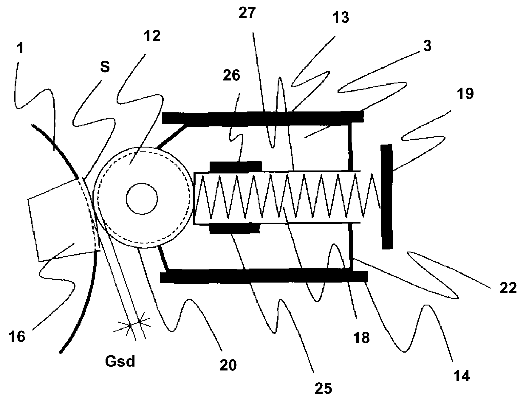
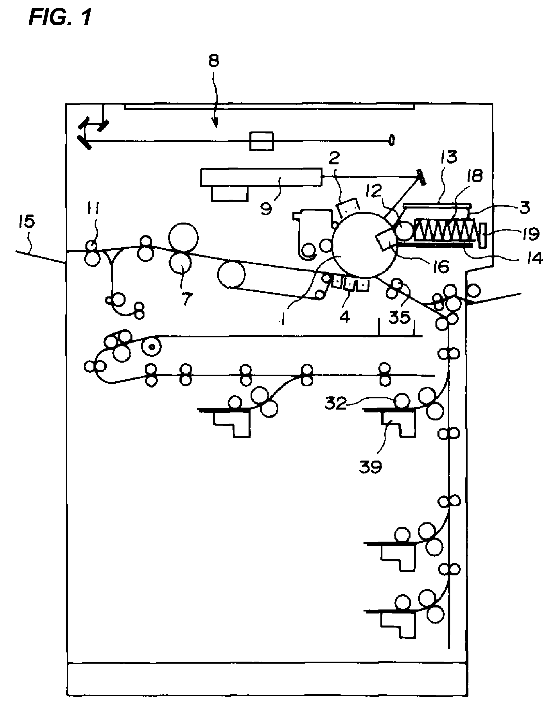
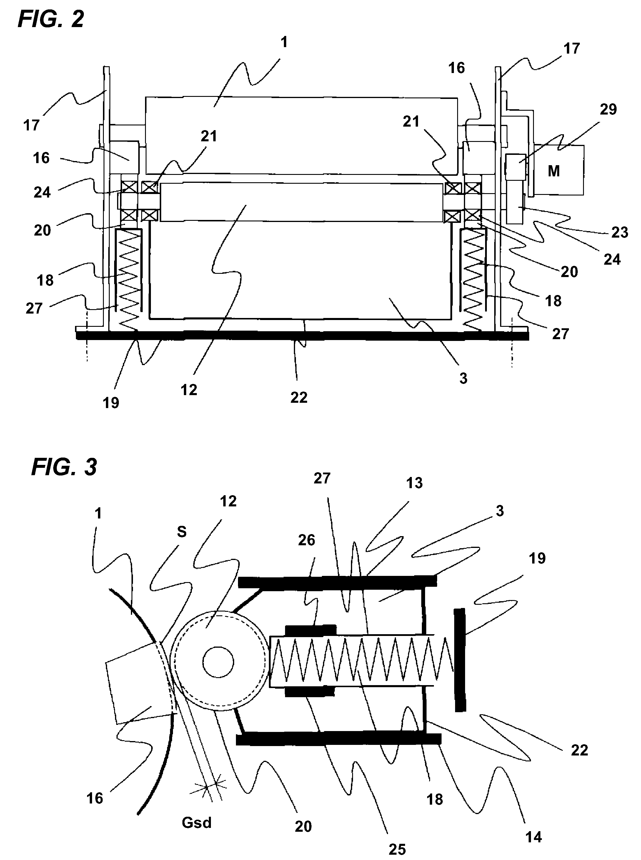
[0036]An embodiment of the present invention will be described below in detail based on the drawings. The same components as the related art are indicated by the same reference numerals. FIG. 1 illustrates a block diagram of an image forming apparatus according to an embodiment of the present invention. FIG. 2 is a schematic plan view of a photosensitive drum and a development sleeve. FIG. 3 is a cross-sectional view of FIG. 2.

[0037]In FIGS. 1 to 3, the image forming apparatus reads the image of an original by an image reading portion 8. The surface of a photosensitive drum 1 as an image bearing member is exposed by an image writing portion 9 by an instruction from a controller (not illustrated) based on the read image data.

[0038]Before exposure, the surface of the photosensitive drum 1 is uniformly charged to a predetermined potential by a charger 2. The uniformly charged photosensitive drum 1 is illuminated with a laser beam by the image writing portion 9. An electrostatic latent ...


PUM


Abstract

An image forming apparatus has an abutment roller which is provided at either end of a developing sleeve in a longitudinal direction and makes an SD gap (Gsd) between a photosensitive drum and a developing sleeve constant, an abutment block which is provided at either end of the photosensitive drum in a longitudinal direction and on which the abutment roller abuts, and a pressing spring which directly presses the abutment roller toward the abutment block. The stability of the SD gap (Gsd) and reduction of the driving load torque of the developing sleeve can be achieved to cope with both high image quality and durability of the image forming apparatus.

Description

BACKGROUND OF THE INVENTION[0001]1. Field of the Invention[0002]The present invention relates to an image forming apparatus, such as a copying machine and a laser beam printer, which allows an electrostatic latent image on a latent image bearing member to be a visible image by a development device.[0003]2. Description of Related Art[0004]As illustrated in FIGS. 7 and 8, an image forming apparatus typically has a photosensitive drum 1 and a development device 3. The development device 3 has a developing sleeve 12. The photosensitive drum 1 and the developing sleeve 12 are arranged so as to constantly hold an SD gap Gsd which is a small gap between both, thereby performing predetermined development. When the SD gap Gsd is varied, poor image formation such as inconsistencies in density in an image can be caused.[0005]The developing sleeve 12 has an abutment roller 20 at either end in a longitudinal direction so as to be rotatably held via a bearing 24, and is rotatably supported by a d...

Claims


Application Information

Patent Timeline
IPC IPC(8): G03G21/16
CPCG03G15/0813
Inventor KATAYAMA, HIROMASA
Owner CANON KK
Learn More