Converter control unit

a control unit and converter technology, applied in the direction of electric generator control, dynamo-electric converter control, dc source parallel operation, etc., can solve the problems of increasing the stability limit of the operation of the power system, the transmission bottleneck and electromechanical oscillation of parts of the electric power system, and the reduction of the operational margin of many power systems world wid

Inactive Publication Date: 2009-03-26
ABB RES LTD
View PDF3 Cites 21 Cited by
  • Summary
  • Abstract
  • Description
  • Claims
  • Application Information

AI Technical Summary

Benefits of technology

[0008]Exemplary embodiments disclosed herein can enable, without incurring heavy infrastructural investments, phasor-based monitoring, protection and control applications in electric power systems equipped with...

Problems solved by technology

In the past years, continued load growth without a corresponding increase in transmission resources has resulted in reduced operational margins for many power systems world wide, and has led to operation of power systems ever closer to their stability limits.
Likewise, load transmission and wheeling of power from distant generators to local load consumers has become common practice, and led to substantially increased amounts of power being transmitted through the existing networks, occa...

Method used


Image

  • Converter control unit
  • Converter control unit

Examples


Embodiment Construction

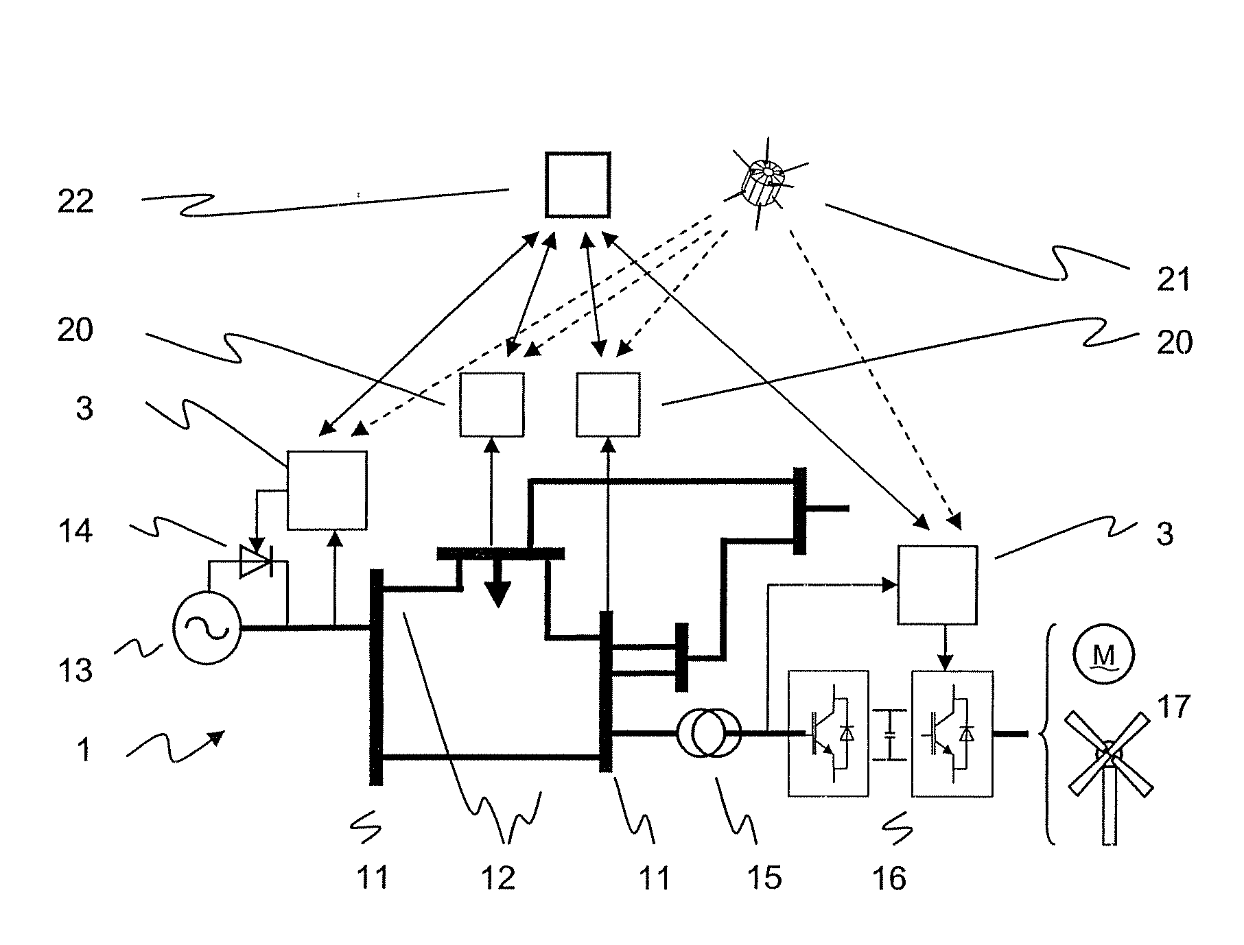
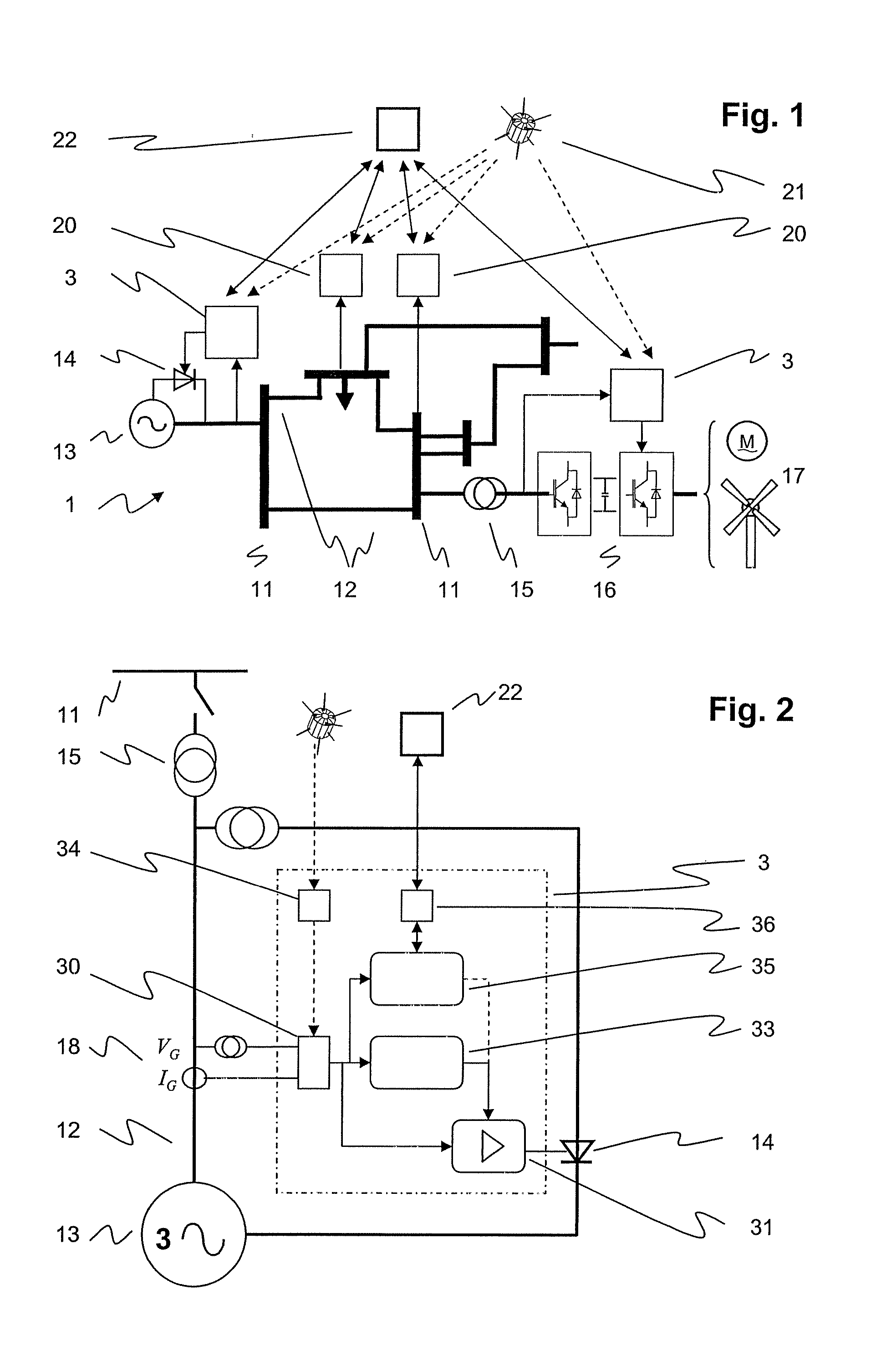
[0016]According to the present disclosure, converter control units are equipped and employed to provide and process phasor data for wide-area monitoring, protection and control functions, thus requiring less dedicated phasor measurement units to be installed in the electric power system. An economy in hardware components can be achieved, as e.g. the housing and a power supply of an individual converter control unit may also be used for accommodating and for supplying power to both a synchronization means providing time-stamps for global time synchronization and a phasor data facility for calculating the time-stamped synchronized phasor data. In addition, the integration of the aforementioned synchronization means and phasor data facility into the converter control unit may comprise implementing the corresponding functionality completely or partly in the existing hardware of the converter control unit.

[0017]In an exemplary method of performing wide-area protection and control applica...


PUM


Abstract

The disclosure relates to a converter control unit or power system stabilizing unit for counteracting oscillations in electric power systems that is equipped and employed to provide and processes information for system-wide monitoring, protection, control and metering. It comprises means for synchronized (e.g. via GPS or another absolute/global time reference) sampling of voltages and/or currents, means for down-sampling in order to decrease the number of samples, and means for calculating phasors, i.e. time stamped amplitude and phase angle of the voltages and/or currents.

Description

RELATED APPLICATIONS[0001]This application claims priority under 35 U.S.C. §119 to EP Application 06405090.9 filed in Europe on Mar. 2, 2006, and as a continuation application under 35 U.S.C. §120 to PCT / CH2007 / 000106 filed as an International Application on Mar. 2, 2007 designating the U.S., the entire contents of which are hereby incorporated by reference in their entireties.TECHNICAL FIELD[0002]The disclosure relates to the field of wide-area monitoring, protection and control of an electric power system. For example, a converter control unit is disclosed for controlling a converter based on power electronic semiconductor components and arranged in the electric power system.BACKGROUND INFORMATION[0003]An electric power system comprises a power transmission and / or distribution network interconnecting geographically separated regions, and a plurality of substations at the nodes of the power network. The substations include equipment for transforming voltages and for switching conne...

Claims


Application Information

Patent Timeline
IPC IPC(8): H02J3/24H02P9/10
CPCH02J3/00Y04S10/265Y02E60/728H02J3/24Y02E60/00Y04S10/00Y04S10/22Y02E40/70H02J3/242
Inventor KORBA, PETRWIESER, RUDOLFPONNALURI, SRINIVASLARSSON, MATSOUDALOV, ALEXANDRETABORDA, JOSESTEIMER, PETER
Owner ABB RES LTD
Why Eureka
Try Eureka