Electric Fireplace Heater Having LED Flame Simulator

Inactive Publication Date: 2009-03-26
CHIU HSIEN JUNG
5 Cites 35 Cited by

AI-Extracted Technical Summary

Problems solved by technology

However, regular bulbs in the conventional fireplace heater illuminate aluminum pieces on a rotating twisted rod to generate flickering flame images, and artificial logs to generate the appearance of burning logs, thereby closely simulating the...

Method used

[0023]When the electric fireplace heater having the LED flame simulator according to the present invention is in operation, the axle of the motor 32 drives the axle sleeve 34 to rotate. Because the axle sleeve 34 is tightly fitted into the cylinder 33, the cylinder 33 is driven to rotate. When the LED light source 4 is turned on, the light emitted by the LED's 42 is projected onto the light-guide plate through the patterned apertures 331 on the cylinder 33. Thus, the shapes of the patterned apertures are cast to form flame images on the light-guide unit 2. Because the rod 41 faces the light-guide unit 2 at a 45-degree angle, the images cast on the light-guide unit 2 are larger than those at other angles. T...

Benefits of technology

[0008]When the motor drives the cylinder to rotate, the light emitted by the LED's is projected onto the light-guide plate through the patterned apertures on the cylinder. The artificial logs are also illuminated by the LED's. Thus, the flickering flame appears on the light-guide plate and the artificial logs look like burning woods. In order to make the flame more realistic, the cylinder according to the present invention can be a transparent tube wrapped with a red glassine, a yellow glassine and a sheet of paper. The paper includes patterned apertures shaped in flame-like S, lightning bolt, etc. The white light and/or other color light emitted by LCD's are projected through the patterned apertures of the cylinder and the shapes of the patterned apertures are projected onto the light-guide plate, thereby generating the images of flickering flames. Otherwise, the light-guide plate dyed red, yellow or other colors similar to the flame can replace the glassines wrapped on the cylinder, and achieve the same simulated effect of the flickering flames.
[0009]In addition, a heating device is mounted on the main body. The heating device includes heating wires, a switch and a blower to deliver heat to the environment. Thus, the fireplace he...

Abstract

An electric fireplace heater having an LED flame simulator includes a main body, a light-guide unit, a roller unit, a plurality of LED light sources, and an electric heating device. The main body includes a frame and artificial logs. The light-guide unit is mounted inside of the main body and behind the artificial logs. The roller unit is mounted inside of the main body and behind the light-guide unit. The roller unit includes a rack, and a cylinder provided with patterned apertures and driven to rotate by a motor. One of the LED light sources is disposed under the artificial logs to simulate burning woods and one of the LED light sources is disposed inside of the cylinder. The light emitted by the LED light source passes through the patterned apertures of the cylinder and is projected onto the light-guide unit, thereby presenting images of simulated flames.

Application Domain

Technology Topic

Image

  • Electric Fireplace Heater Having LED Flame Simulator
  • Electric Fireplace Heater Having LED Flame Simulator
  • Electric Fireplace Heater Having LED Flame Simulator

Examples

  • Experimental program(1)

Example

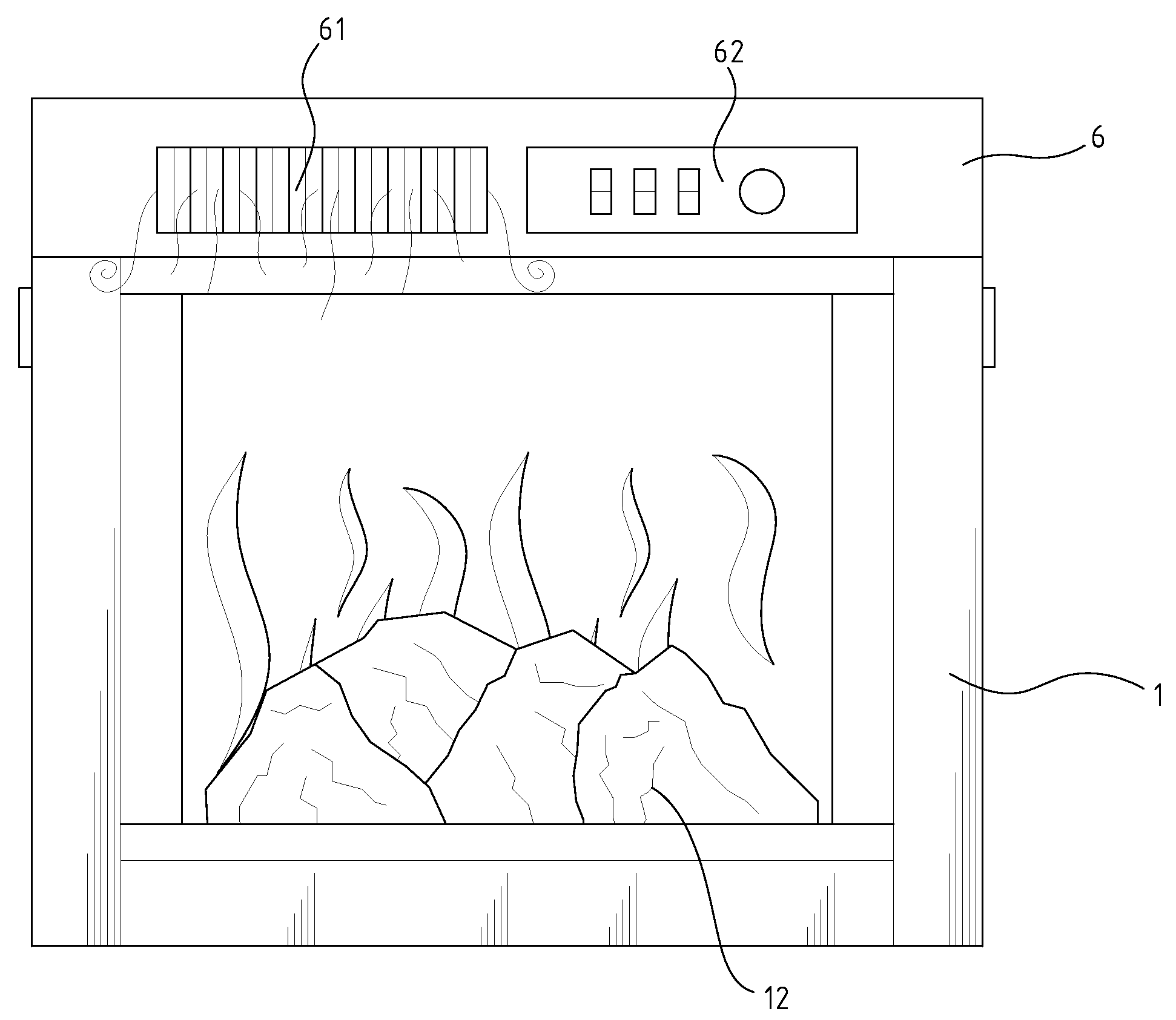
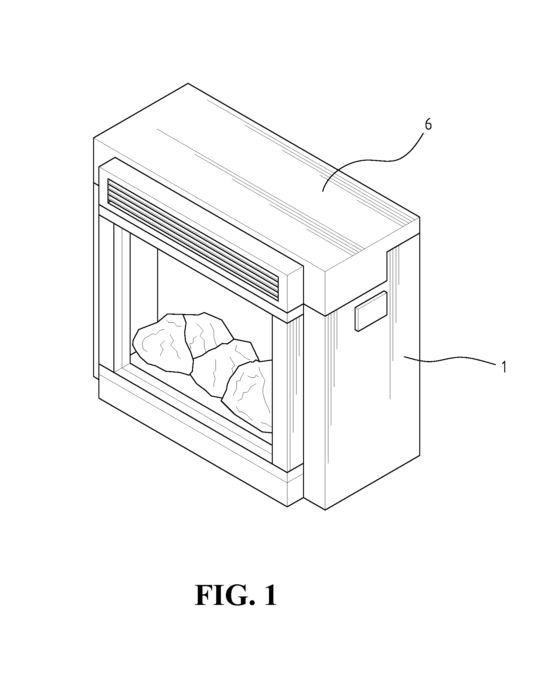
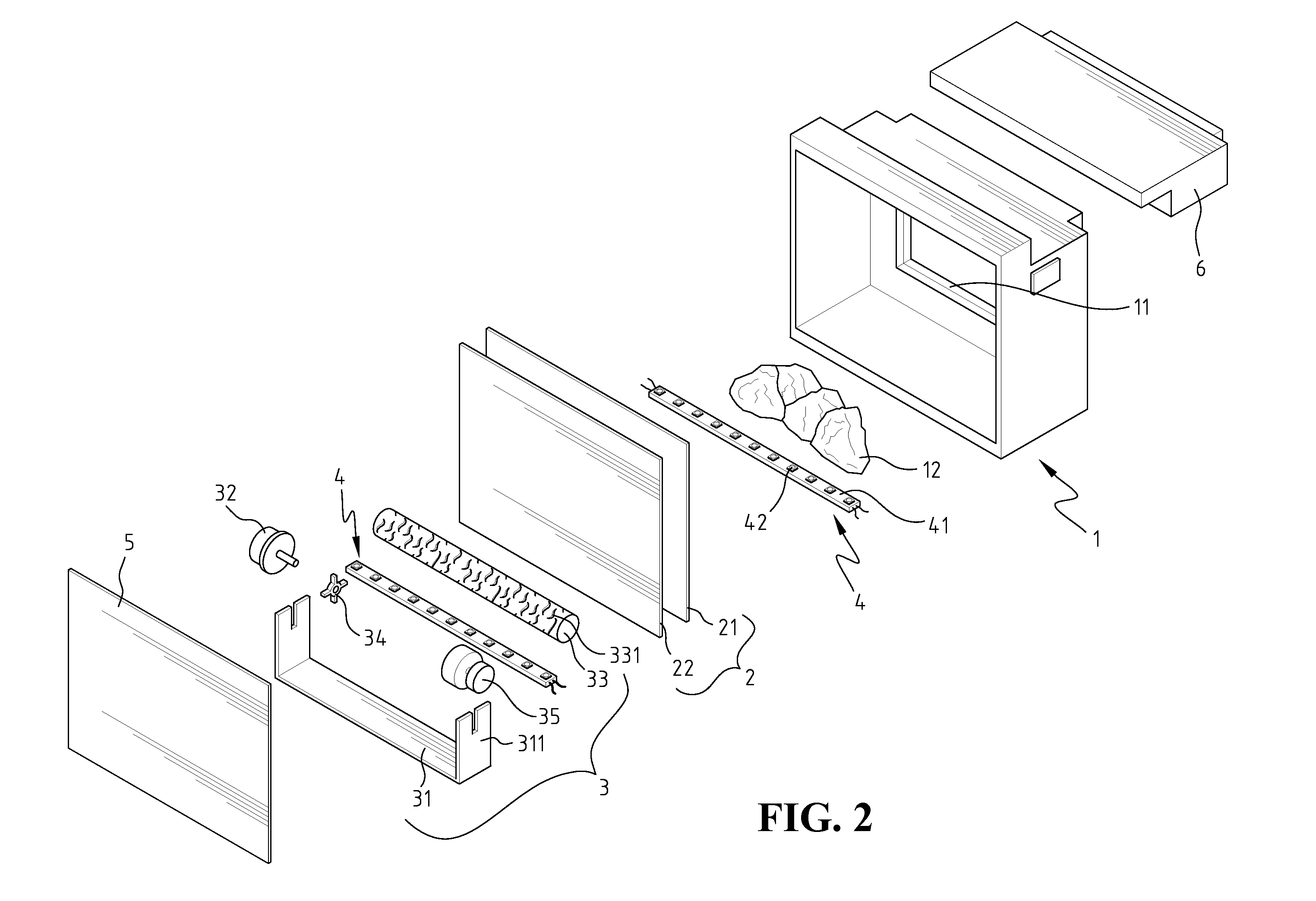
[0016]Referring to FIGS. 1 and 2, an electric fireplace heater having an LED flame simulator in accordance with the present invention includes a main body 1, a light-guide unit 2, a roller unit 3, a plurality of LED light sources 4, and an electric heating device 6.
[0017]The main body 1 is a case made of wood or metal plate. The main body 1 includes a frame 11 and artificial logs 12 disposed at a bottom of the frame 11. The artificial logs are made of plastic or other translucent material. The light-guide unit 2, the roller unit 3 and LED light sources 4 are disposed inside the main body 1. A cover 5 is mounted at a back of the main body and seals the light-guide unit 2, the roller unit 3 and LED light sources 4 in the main body 1.
[0018]The light-guide unit 2 is disposed behind the artificial logs 12 and divides the space inside the main body 1 into a front space and a rear space. The artificial logs 12 are disposed in the front space and the roller unit 3 is disposed in the rear space. The light-guide unit 2 includes a light-guide plate having a transparent plate 21 and a matte translucent film 22 attached to a back surface of the transparent plate 21. The transparent plate 21 is transparent or translucent. The transparent plate 21 may be made of glass or acrylic glass.
[0019]The roller unit 3 is disposed inside the main body 1 and behind the light-guide unit 2. The roller unit 3 includes a rack 31, a motor 32, an axle sleeve 34 mounted on an axle of the motor 32, a fixing cap 35 and a cylinder 33. The rack 31 is a narrow U shaped frame and made of metal. The rack 31 includes a pair of brackets 311. The axle sleeve 34 is ring shaped and includes a plurality of ribs at the circumference thereof. The diameter of the fixing cap 35 is slightly larger than that of the cylinder 33, and the fixing cap has an engaging notch (not shown in the figures) at the center thereof. The cylinder 33 is a transparent tube wrapped in a red glassine and a yellow glassine which generate the color of the flames. A thick sheet of glossy paper or plastic, which includes various patterned apertures 331 to simulate flames, is wrapped around the glassiness The patterned apertures may be in thunderbolt shapes or in S shapes. The light-guide unit 2 may be dyed in red, yellow, or other colors similar to the color of the flames to replace the glassiness
[0020]The LED light source 4 includes a rod 41 and a plurality of light-emitting diodes (LED's) 42, which are mounted on the rod and connected with electric wires and a switch. The switch can turn on and off and control brightness of the LED's 42. The colors of the emitted light by the LED's 42 can be any colors.
[0021]Referring to FIGS. 2 and 3, the U-shaped rack 31 is mounted on the main body 1 and behind the light-guide unit 2. The axle sleeve 34 is tightly fitted into one end of the cylinder 33 and the ribs of the axle sleeve 34 are contacted with the inner surface of the cylinder 33. One end of the LED light source 4 is tightly fitted into the notch of the fixing cap 35, and the rod 41 faces the light-guide unit 2 at a 45-degree angle. The motor 32 is then mounted on the rack 31. The axle of the motor 32 passes through the brackets 311 and is connected with the axle sleeve 34, which is fitted into the cylinder 33. Thus, a first end of the cylinder 33 is connected with the motor 32. The LED light source 4 tightly fitted into the fixing cap 35 is inserted into a second end of the cylinder 33. The fixing cap 35 loosely covers the second end of the cylinder 33 and stays stationary without rotating with the cylinder 33. The fixing cap 35 is then fixed on the bracket 311 by screws. Therefore, the roller unit 3 and the LED light source 4 are assembled together. The LED light source 4 is stationary and the cylinder 33 can be driven to rotate by the motor 32.
[0022]The electric heating device 6 is mounted on the main body 1. The electric heating device 6 includes a blower to send out the warm air from air outlet 61 and a control panel 62 to control the speed and temperature setting of the warm air.
[0023]When the electric fireplace heater having the LED flame simulator according to the present invention is in operation, the axle of the motor 32 drives the axle sleeve 34 to rotate. Because the axle sleeve 34 is tightly fitted into the cylinder 33, the cylinder 33 is driven to rotate. When the LED light source 4 is turned on, the light emitted by the LED's 42 is projected onto the light-guide plate through the patterned apertures 331 on the cylinder 33. Thus, the shapes of the patterned apertures are cast to form flame images on the light-guide unit 2. Because the rod 41 faces the light-guide unit 2 at a 45-degree angle, the images cast on the light-guide unit 2 are larger than those at other angles. The rotating cylinder 33 makes the images of the flames projected on the light-guide unit 2 to move to and fro. Thus, it looks like flickering flames. Referring to FIG. 2, the LED light source 4 disposed under the artificial logs 12 illuminates the light-pervious artificial logs 12, which simulates real blazing logs and makes the simulated flames more realistic. The brightness of the LED light sources 4 behind the light-guide unit 2 and under the artificial logs 12 can be controlled synchronized. The multiple cylinders 33 are possible. The fireplace heater may include a plurality of cylinders 33, thereby interlacing the flame images from various cylinders 33. The images of the flames will be more realistic.
[0024]Referring to FIG. 4, the electric fireplace heater according to the present invention includes the main body 1, the artificial logs 12 disposed inside the main body 1, the light-guide unit 2 behind the artificial logs 12 and the electric heating device 6. When the electric fireplace heater is in operation, the heater presents the simulated red burning artificial logs 12 and flickering flame images on the light-guide unit 2, and blows out warm air from the electric heating device 6. Therefore, the electric fireplace heater having the LED flame simulator according to the present invention flickers and glows like the real thing, and brings warmth to the room.
[0025]Although the present invention has been described with reference to the preferred embodiment thereof, it is apparent to those skilled in the art that a variety of modifications and changes may be made without departing from the scope of the present invention which is intended to be defined by the appended claims.

PUM

no PUM

Description & Claims & Application Information

We can also present the details of the Description, Claims and Application information to help users get a comprehensive understanding of the technical details of the patent, such as background art, summary of invention, brief description of drawings, description of embodiments, and other original content. On the other hand, users can also determine the specific scope of protection of the technology through the list of claims; as well as understand the changes in the life cycle of the technology with the presentation of the patent timeline. Login to view more.

Similar technology patents

Adjustable cabinet for biological test

InactiveUS20150323443A1Long life spanFluorescence/phosphorescenceBiological testBody type
Owner:SMOBIO TECH

Array management device, array management method and integrated circuit

InactiveUS20130219212A1Unnecessary executionLong life-spanRedundant hardware error correctionWaiting periodOperating system
Owner:PANASONIC CORP

Container arrangement tag having positioning and electronic sealing function

ActiveUS20090151406A1Large storage volumeLong life spanBurglar alarm by openingLarge containersGps satellitesSatellite
Owner:SHANGAI INT PORT GRP

Switch valve

ActiveUS20110048563A1Long life-spanBlocking performance is highOperating means/releasing devices for valvesEqualizing valvesInterior spaceEngineering
Owner:ULVAC INC

Classification and recommendation of technical efficacy words

  • Long life-span
  • Energy save

Lighting Assembly

ActiveUS20140293595A1Long life spanEnhance lightPlanar light sourcesLight source combinationsEngineeringStraight path
Owner:DVA HLDG LLC

Projection display

ActiveUS20050057731A1Long life spanProjectorsOptical articlesIntegratorOptoelectronics
Owner:SAMSUNG ELECTRONICS CO LTD

Projection display

InactiveUS20050088624A1Long life spanProjectorsOptical elementsIntegratorBroadside radiation
Owner:SAMSUNG ELECTRONICS CO LTD

Programmable energy saving register vent

InactiveUS20070298706A1Energy saveReduce amount of energyDucting arrangementsMechanical apparatusLouverEngineering
Owner:SPRINGFIELD ACQUISITION CO LLC
Why Eureka
Try Eureka