Parked aircraft climate control system and method

a climate control system and parked aircraft technology, applied in the field of parked aircraft climate control system and method, can solve the problems of unit shutdown, refrigeration system, and conventional aircraft conditioned air supply system, and achieve the effect of maintaining system operation and reducing the heat-removal capacity of the system

Inactive Publication Date: 2009-04-02
HOBART BROS
View PDF15 Cites 48 Cited by
  • Summary
  • Abstract
  • Description
  • Claims
  • Application Information

AI Technical Summary

Benefits of technology

[0006]In accordance with certain aspects of the technique, a refrigeration system for supplying air to a parked aircraft is provided that includes parallel compressors, one or more of which can be operated at any time based upon temperatures and actual temperatures of air being supplied to the aircraft, and upon the thermal load. Moreover, the system may include multiple fans for one or more condensers, which may be individually controlled based upon refrigerant pressures. As thermal loads increase, pressures may be monitored or pressure switches may be set and controlled to interrupt operation of one of the compressors, thereby reducing the heat-removal capacity of the system, while maintaining system operation.

Problems solved by technology

A drawback of conventional aircraft conditioned air supply systems, particularly of refrigeration systems, is their reaction to variable thermal loads caused by high or low ambient conditions.
However, when external temperatures rise significantly, adding to the thermal load on the refrigeration units, excessive refrigerant pressures may be encountered that force the units to shut down, significantly reducing or interrupting the flow of conditioned air to the aircraft.

Method used


Image

  • Parked aircraft climate control system and method
  • Parked aircraft climate control system and method
  • Parked aircraft climate control system and method

Examples


Embodiment Construction

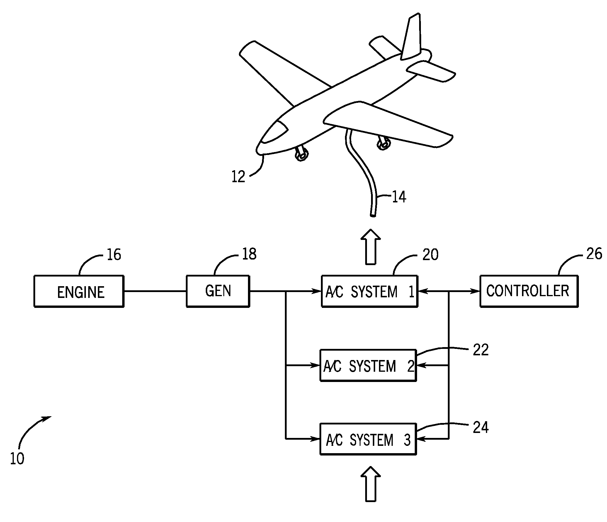
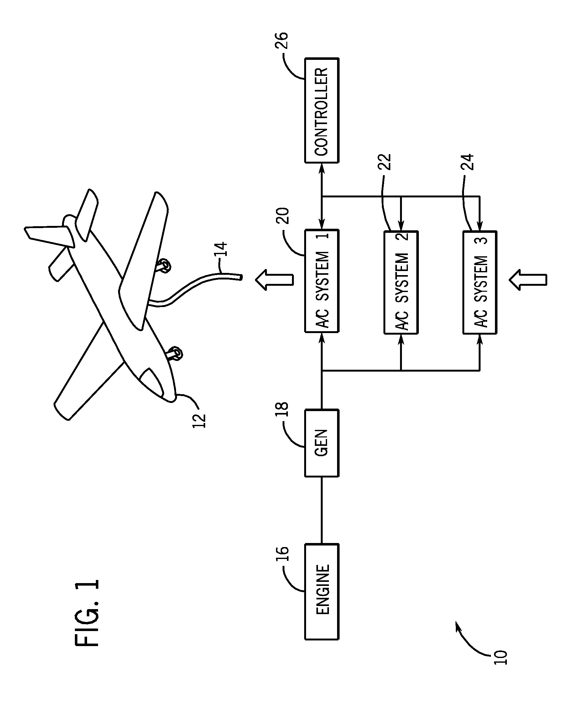
[0012]Turning now to the drawings, and referring first to FIG. 1, an aircraft air conditioning system 10 is illustrated diagrammatically. The system made to be designed as a stationary or mobile system that can be run electrically from a connection to the power grid, or by an integrated or separate power supply. In many applications, the system can be designed as a cart which can approach an aircraft 12 and supply conditioned air by a conduit 14 which is coupled between the air conditioning system and the aircraft.

[0013]In the embodiment illustrated in FIG. 1, the system is operated by power provided by an engine-driven generator set. An internal combustion engine 16, such as a gasoline or diesel engine drives a generator 18 which will typically be associated with appropriate control circuitry for providing output power for the air conditioning units. The air conditioner itself may include one or a series of air conditioning or refrigeration units as indicated by reference numerals ...


PUM


Abstract

A conditioned air delivery system is provided for parked aircraft. The system can accommodate elevated thermal loads while maintaining operation, albeit with reduced flow rates or slightly elevated temperatures. When temperature set points are not reached or cannot be maintained, a second compressor of a refrigeration unit is operated in parallel with a first compressor. When refrigerant pressure becomes excessive, a second fan is operated that is associated with a condenser of the system. Still higher pressures, indicative of higher thermal loads, can cause the system to shut down operation of one of the compressors, reducing the overall cooling capacity of the system, while maintaining the supply of refrigerated air to the aircraft. The airflow may be reduced to maintain an air temperature at or near the desired temperature. Coordination of several parallel and redundant refrigeration units may be provided with a single blower and coordinated control.

Description

BACKGROUND[0001]The present invention relates generally to systems for providing fresh air to aircraft when parked at a location on the ground. More particularly, the invention relates to a system that can adaptively regulate its operation during periods of considerable thermal load to maintain operation at a reduced level rather than interrupting operation completely.[0002]Various air conditioning systems have been developed for providing conditioned air to aircraft. During flight, power plants (engines) used to drive the aircraft also generate power that can drive on-board conditioned air circulation systems. When parked on the ground, however, conditioned air may be supplied by external means. Air conditioning or refrigeration units may be provided adjacent to such aircraft and coupled to the aircraft by air conduits. Such refrigeration systems, may be either electrically powered or engine-driven. The thermal load encountered by the refrigeration systems, however, can vary greatl...

Claims


Application Information

Patent Timeline
Patent Type & Authority Applications(United States)
IPC IPC(8): B60H1/32F25B5/02F25B49/02
CPCB64F1/362F25B2500/27F25B49/027F25B2400/075F25B2500/07F25B2600/0251F25B2600/111F25B2600/112F25B2700/1931F25B2700/1933F25B2700/21152F25B2700/21161B64F1/364F24F2011/0067F25B2400/06F25B6/02F25B5/04F25B2500/26F25B49/022F24F11/54
Inventor MEIER, RICHARDRAJASEKARAN, VARUNQUINONES, DANIEL
Owner HOBART BROS
Why Eureka
Try Eureka