Water reduction mechanism for an internal combustion engine

a technology of internal combustion engine and water reduction mechanism, which is applied in the direction of machines/engines, mechanical equipment, transportation and packaging, etc., can solve the problems of increasing the degradation rate of various engine components, increasing the wear and tear of engine components, and oil starvation, so as to reduce the viscosity of oil, reduce the formation of ice, and reduce the effect of oil degradation

Inactive Publication Date: 2012-05-10
FORD GLOBAL TECH LLC
View PDF13 Cites 2 Cited by
  • Summary
  • Abstract
  • Description
  • Claims
  • Application Information

AI Technical Summary

Benefits of technology

[0006]In this way, by increasing the temperature of the engine, and thus the oil, it may be possible to evaporate the condensed water in the oil and thereby remove water from the oil, decreasing oil degradation. Additionally, or alternatively, it may be possible to reduce ice formation that may block an oil pick-up tube. Likewise, it may be possible to reduce oil viscosity to maintain system operation. In one example, the oil temperature may be increased via a block heater, such as used for improving cold starting in cold climates. In another example, the oil temperature may be increased by adjusting the engine cooling system. In still another example, the oil temperature may be increased by an oil heater in the oil pan. Still other examples are also possible as described herein.

Problems solved by technology

Excessive water build-up can degrade the oil and thus lead to increased engine component wear.
In turn, increased component wear may increase degradation rates of various engine components, such as bearings, piston rings, intake valves, camshafts, etc.
Increased water in the oil may also lead to oil starvation caused by ice forming over an oil pickup tube.
As another example, oil starvation may be caused by the oil-water mixture viscosity becoming too low to support oil pump operation.
However, the operator may be unwilling, or unable, to provide the requested operation.
For example, the operator may be unwilling to consume additional fuel to provide the requested operation.
As another example, the operator may have other scheduled activities to carry out, or the operator may be stuck in traffic.
Finally, in hydrogen-fuelled engines, because of the large volume of water by-products produced, simply extending driving operation of the vehicle may exacerbate the water contamination of the oil rather than reduce it.

Method used


Image

  • Water reduction mechanism for an internal combustion engine
  • Water reduction mechanism for an internal combustion engine
  • Water reduction mechanism for an internal combustion engine

Examples


Embodiment Construction

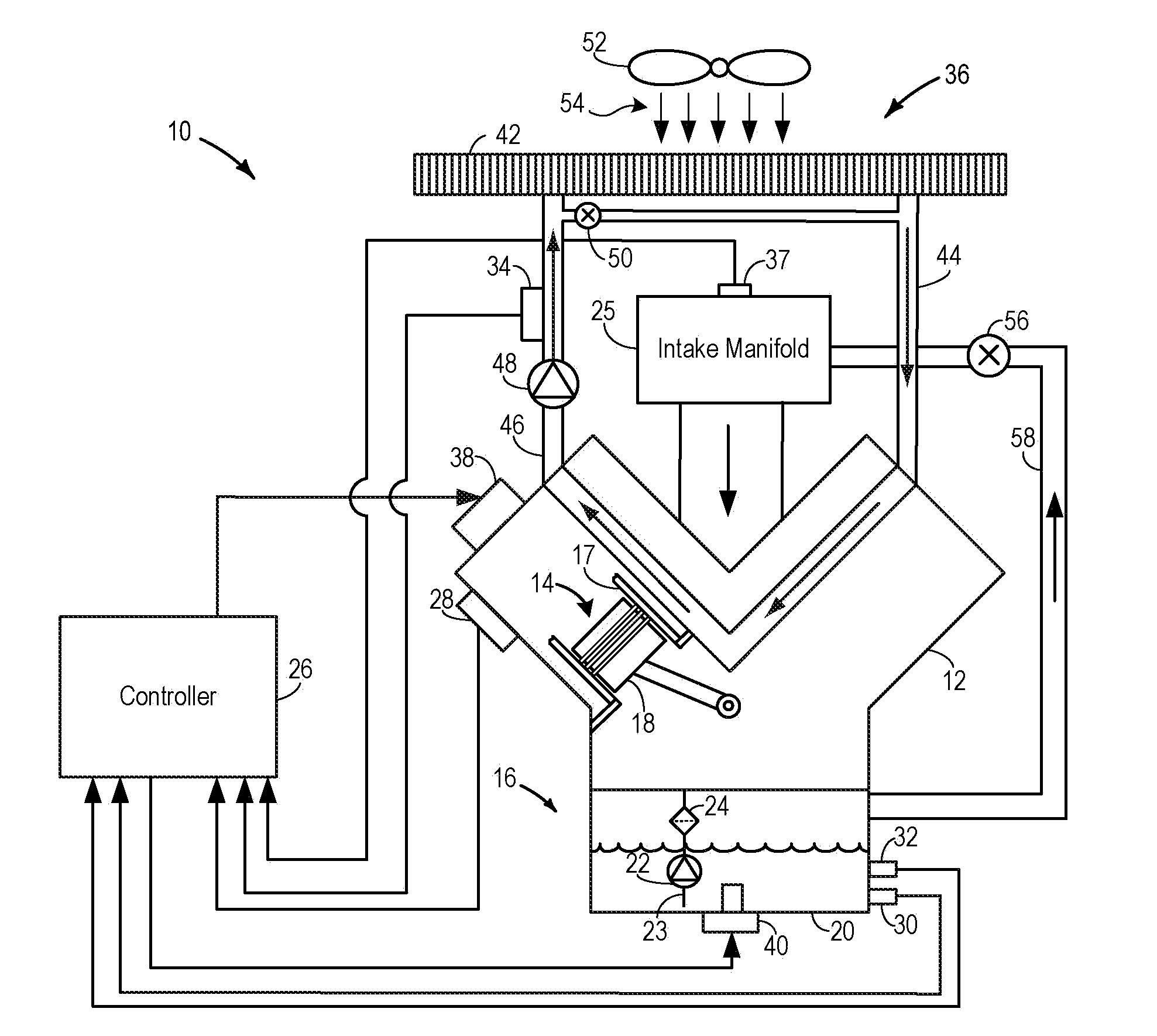
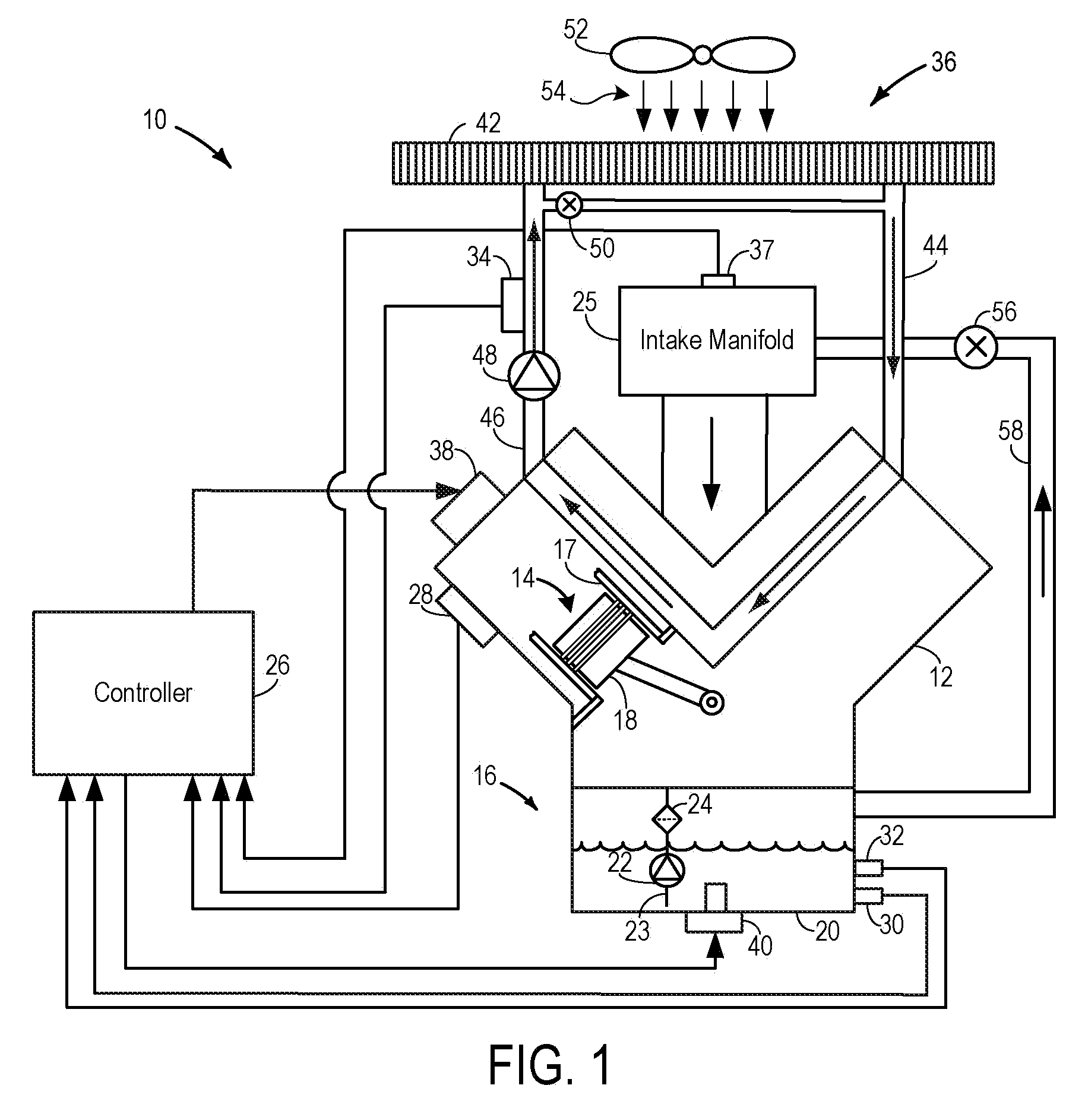
[0012]Hydrogen fuel may be used in internal combustion engines. Due to the characteristics of the hydrogen combustion process, an increased amount of water may be generated as a by-product of combustion during operation of the engine. The water may then condense and migrate into the engine oil. The systems and methods, described herein, show various examples of reducing water contamination of engine oil by increased temperature of the engine and / or oil to thereby evaporate the water and pass it into the intake manifold, for example.

[0013]In some examples, the engine disclosed herein may use hydrogen as its primary fuel source. In other examples, the engine may use various mixtures of hydrogen and another fuel, such as gasoline. However, various other fuels may be used, such as other fuels that may produce increased water condensate in the engine oil.

[0014]FIG. 1 shows a schematic diagram of an internal combustion engine 10 which may be included in a propulsion system of a vehicle. T...


PUM


Abstract

A system for an engine includes an engine block having a cylinder, an oil delivery system including an oil reservoir at least partially enclosing an oil emulsion and providing lubricating oil to at least one cylinder, and a controller configured to adjust the heat delivered to the engine via a heat adjustment mechanism in response to a concentration of water in the oil emulsion.

Description

BACKGROUND / SUMMARY[0001]Internal combustion engines utilize oil for various functions, including lubrication, cooling, etc. The oil can be circulated through various engine passages from a common reservoir, such as an oil pan. Degradation of the engine oil may occur for a variety of reasons such as due to water build-up in the oil and so on. For example, water formed as a byproduct of combustion can condense and migrate into the engine oil. Additionally, engines combusting hydrogen fuel, for example, can produce significantly more water than engines combusting gasoline.[0002]Excessive water build-up can degrade the oil and thus lead to increased engine component wear. In turn, increased component wear may increase degradation rates of various engine components, such as bearings, piston rings, intake valves, camshafts, etc. Increased water in the oil may also lead to oil starvation caused by ice forming over an oil pickup tube. As another example, oil starvation may be caused by the ...

Claims


Application Information

Patent Timeline
Patent Type & Authority Applications(United States)
IPC IPC(8): F02B43/10F01M13/00B60H1/03
CPCF01M5/001F01M5/021F01M2011/148F01M2011/146F01M11/10
Inventor THROOP, MEDVILLE JAYDENLINGER, ADAMBASU, AMIYO K.
Owner FORD GLOBAL TECH LLC
Why Eureka
Try Eureka