
Tire inflation control method and apparatus

a technology of tire inflation and control method, which is applied in the direction of tire measurement, transportation and packaging, vehicle components, etc., can solve the problems of diaphragm movement and tire pressure increas

Inactive Publication Date: 2009-04-02
KALAVITZ MICHAEL V
View PDF32 Cites 60 Cited by
  • Summary
  • Abstract
  • Description
  • Claims
  • Application Information

AI Technical Summary

Benefits of technology

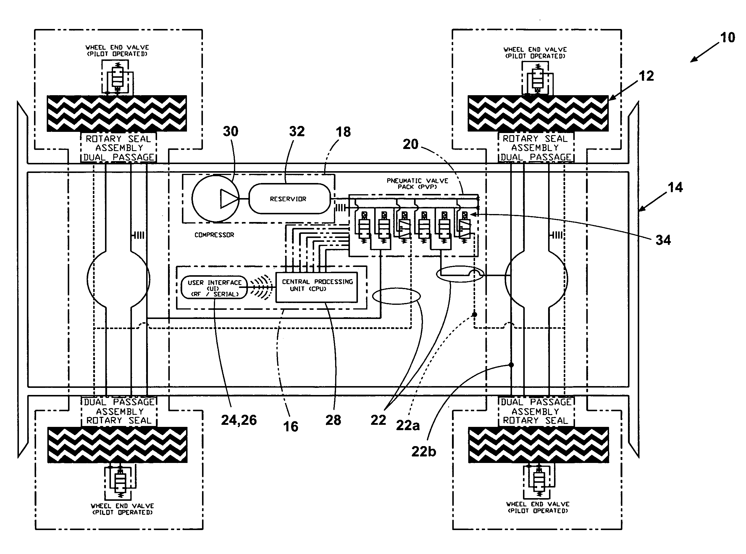
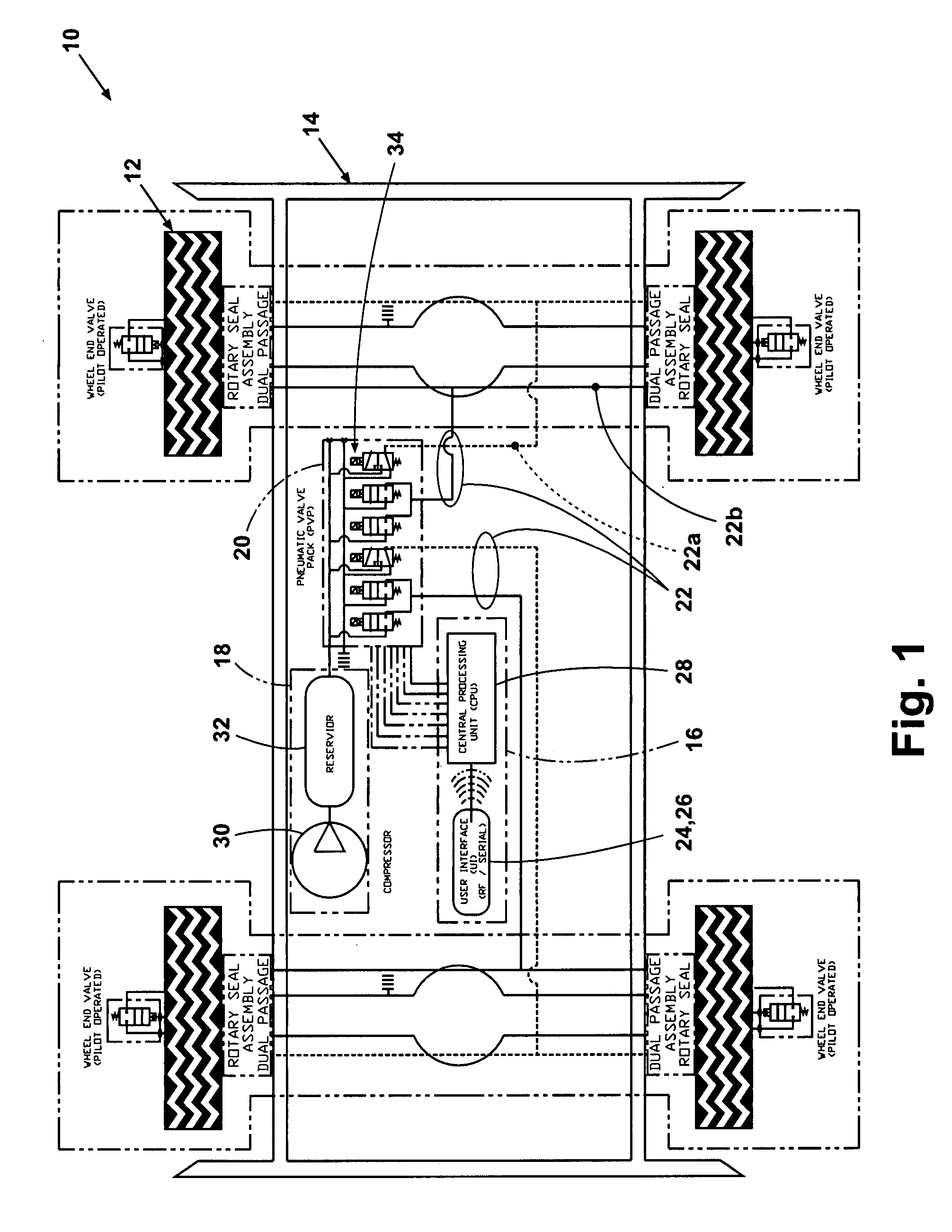
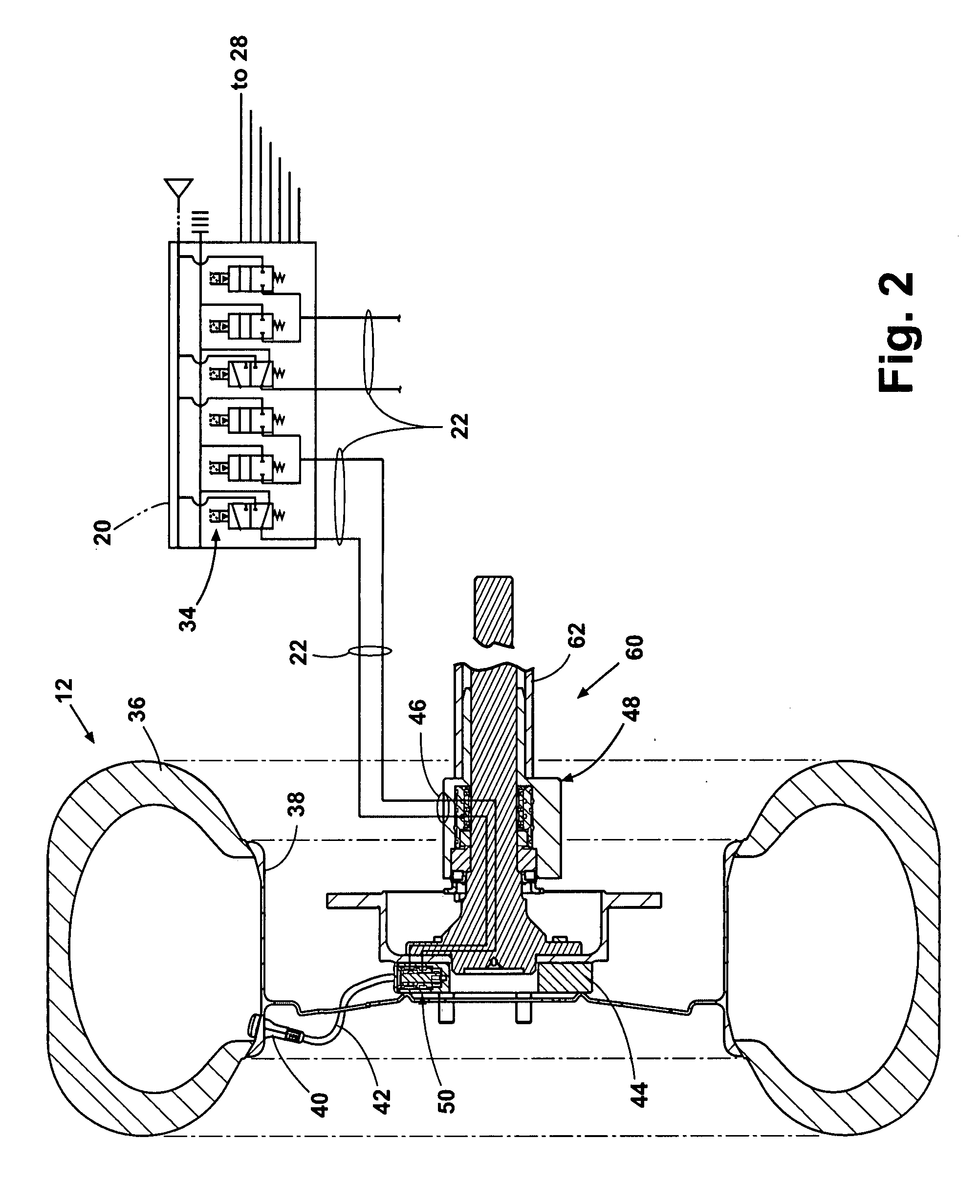
[0007]According to one form of the invention, an apparatus is provided for controlling the tire pressure of a vehicle. The invention includes a housing having first and second ports, and a member journaled within the housing. The housing and the journaled member rotate with respect to one another. Depending on the specific design as described in more detail below, the housing or the journaled member may be driven. The journaled member includ...

Problems solved by technology

When the vehicle was loaded more heavily, the air pressure within the pneumatic suspension system increased causing the diaphragms to move and increase the tire pressure.

Method used


Image

  • Tire inflation control method and apparatus
  • Tire inflation control method and apparatus
  • Tire inflation control method and apparatus

Examples


Embodiment Construction

[0023]For purposes of the following description, the terms “upper,”“lower,”“right,”“left,”“rear,”“front,”“vertical,”“horizontal,” and derivatives and synonyms thereof shall relate to the invention as displayed in the respective figure referenced in that portion of the detailed description. However, it is to be understood that the invention may assume various alternative orientations, except where expressly specified to the contrary. It is also to be understood that the specific devices and processes illustrated in the attached drawings and described in the following specification are simply exemplary embodiments of the inventive concepts defined in the appended claims. Specific dimensions and other physical characteristics relating to the embodiments disclosed herein are not to be considered as limiting, unless the specification and claims expressly state otherwise.

[0024]The reader can obtain a better understanding of the invention by reference to the drawing figures, and in particu...


PUM


Abstract

An apparatus and method are provided for controlling the air pressure within one or more tires on a vehicle. Means are provided for controlling air pressure dynamically or manually in response to road conditions. Instrumental in the invention is the ability to control the air pressure at each wheel from a remote location using positive control that substantially reduces the chance leaks anywhere else in the system would result in inadvertent flat tires.

Description

BACKGROUND OF THE INVENTION[0001]1. Field of the Invention[0002]This invention relates generally to tire pressure control devices, and more particularly to a tire pressure control system for inflating and deflating one or more tires on the vehicle from within the passenger compartment of the vehicle.[0003]2. Description of the Related Art[0004]Tire pressure control systems have been used in the past to control tire pressure on a vehicle in order to affect how the vehicle behaves or responds to road conditions. For example, tire pressure is most often adjusted in response to loads of transport vehicles. Tire pressure is also adjusted to change the size of the tire footprint depending upon the road surface. For example, tire pressure may be reduced to place more surface area of the tread in contact with loose aggregate such as sand, mud or dirt. Tire pressure may be increased to place less tread in contact with hard surfaces such as asphalt or concrete when the vehicle is traveling at...

Claims


Application Information

Patent Timeline
IPC IPC(8): B60C23/10
CPCB60C23/00318B60C23/00336B60C23/00354B60C23/00363B60C23/00372B60C23/0039
Inventor KALAVITZ, MICHAEL V.
Owner KALAVITZ MICHAEL V
Learn More