
Recording tape cartridge

a tape cartridge and tape body technology, applied in the field of recording tape cartridges, can solve the problems of restricted movement of the guard portions of the leader member towards the opening side of the case, and achieve the effect of ensuring the strength of the case, preventing the opening, and requiring the strength level

Active Publication Date: 2009-04-02
FUJIFILM CORP
View PDF8 Cites 5 Cited by
  • Summary
  • Abstract
  • Description
  • Claims
  • Application Information

AI Technical Summary

Benefits of technology

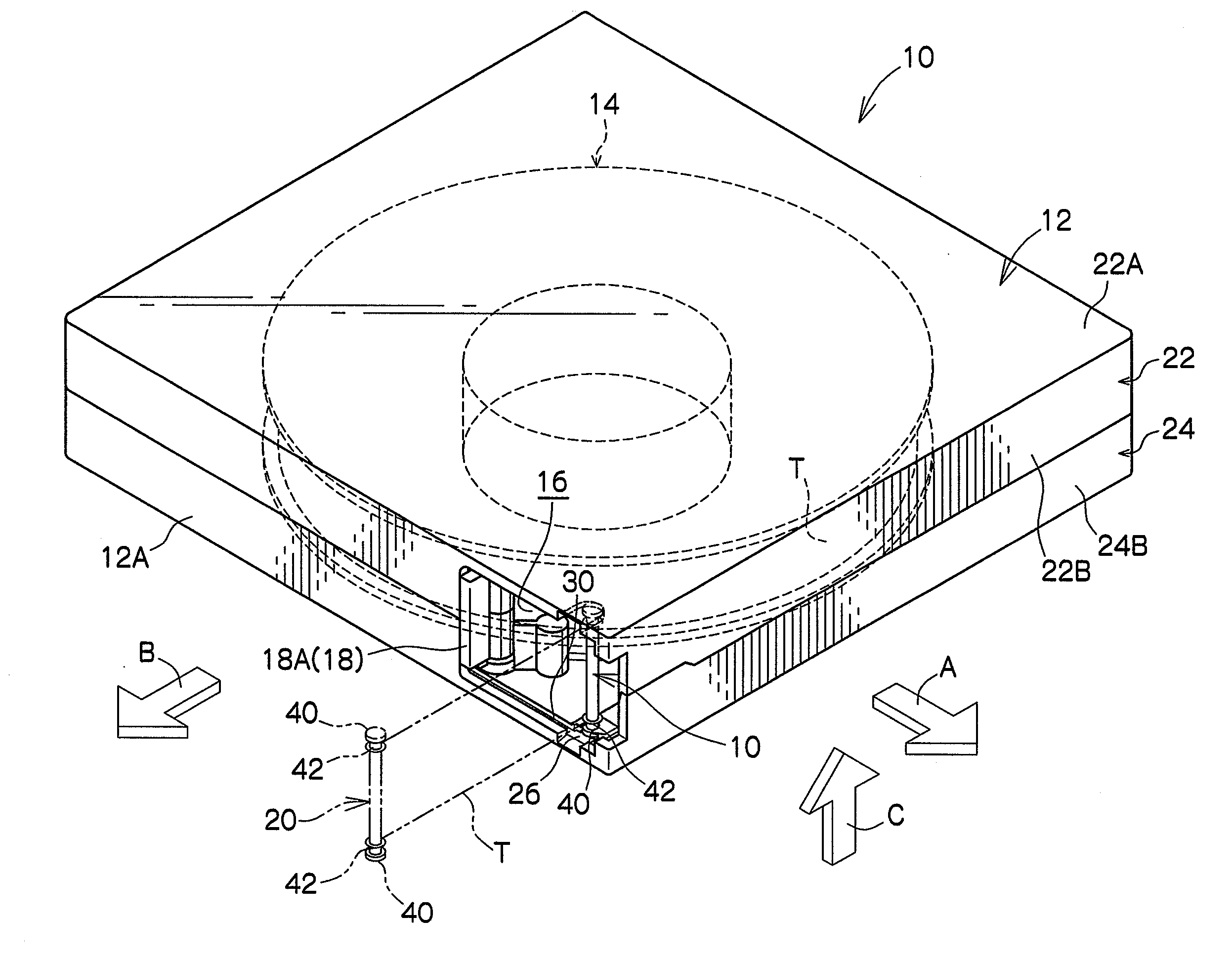
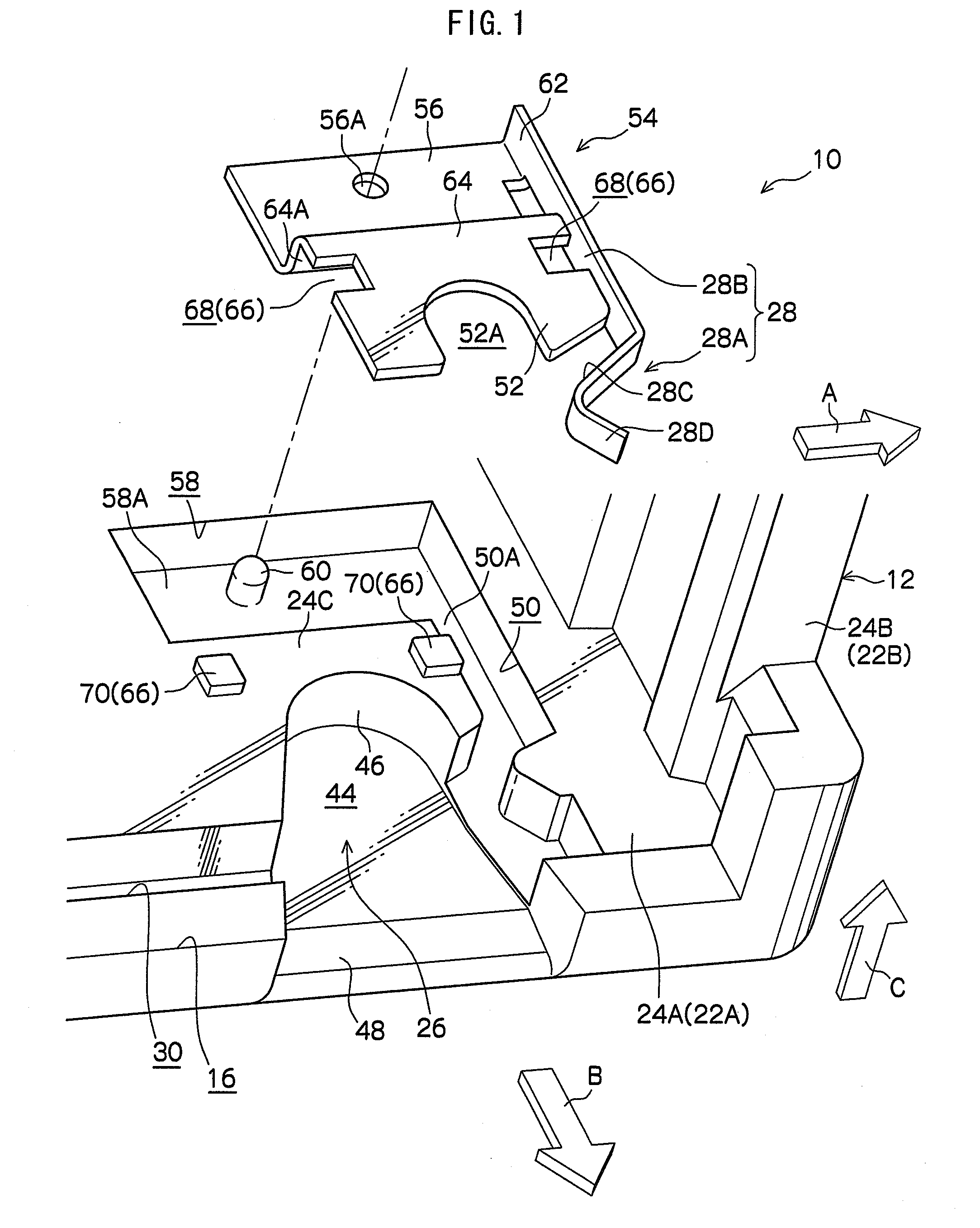
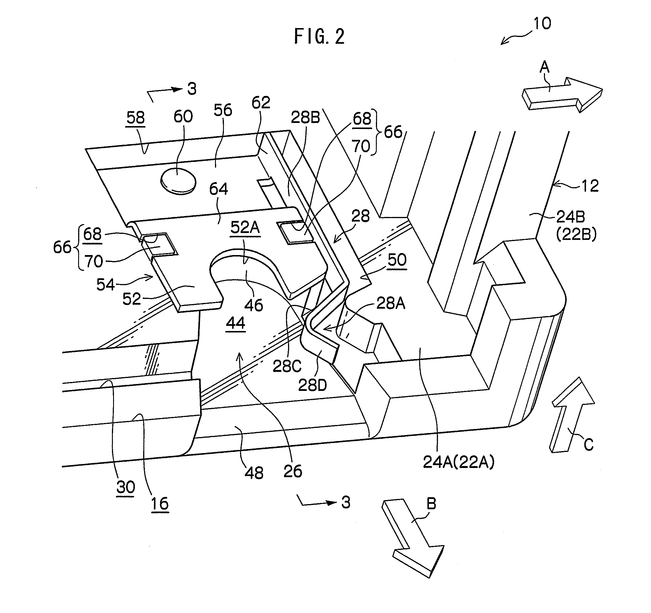
[0009]In the above first aspect of the tape cartridge of the present invention, while the recording tape is housed in the case, guard portions of a leader member, which are disposed at outer sides of either edge in a width direction of the recording tape, are inserted into leader receiving portions, and are also covered by overhanging portions of a leader holding member. Further, movement of the guard portions of the leader member towards the case opening side is restricted by retaining spring portions of a leader holding member. In this recording tape cartridge, when deformation occurs at the opening in an opening direction thereof, since the guard portions of the leader member engage with the overhanging portions, deformation of the case opening in the opening direction can be suppressed. When the recording tape is pulled out of the case, the leader member moves towards the case opening side, the guard portion is separated from the leader receiving portion, and following this, the recording tape is pulled out of the case in conjunction with the movement of the leader member.
[0020]The recording tape cartridge of the present invention described above has the advantageous effect of ensuring the strength of the case while also preventing a case opening portion from widening.

Problems solved by technology

Further, movement of the guard portions of the leader member towards the case opening side is restricted by retaining spring portions of a leader holding member.

Method used


Image

  • Recording tape cartridge
  • Recording tape cartridge
  • Recording tape cartridge

Examples


second embodiment

[0077]FIG. 9 shows an exploded perspective view of the leader pin receiving portions 26 of a recording tape cartridge 80 according to a second embodiment of the invention, and FIG. 10 shows a perspective view of the pin receiving portions 26 of the recording tape cartridge 80. As shown in these drawings, the recording tape cartridge 80 differs from the tape cartridge 10 according to the first embodiment in that, instead of the overhanging portion 52 (overhanging connection portion 64) being disposed on the general surface 24C of the lower case 24, the overhanging portion 52 is inserted in recessed position-fixing portion 82 of the lower case 24.

[0078]As shown in FIG. 9, recessed position-fixing portion 82, which forms part of the position-fixing portion 84 of the recording tape cartridge 80, is formed between recessed housing portion 44 and recessed fixing portion 58, and is recessed with respect to the general surface 24C of the lower case 24 only to the extent of the thickness of ...

third embodiment

[0081]FIG. 11 shows an exploded perspective view of the pin receiving portions 26 that form part of the recording tape cartridge 90 according to the third embodiment of the present invention, and FIG. 12 shows a perspective view of the pin receiving portions 26 of the recording tape cartridge 90. FIG. 13 shows a sectional view along line 13-13 of the pin receiving portion 26 of the recording tape cartridge 90. As is shown in these drawings, the recording tape cartridge 90 differs from the recording tape cartridge 10 of the first embodiment in that, instead of a leader holding member 54 in which the overhanging portion 52 and the fixed portion 56 are connected via the overhanging connection portion 64 which includes step portion 64A, the recording tape cartridge 90 is provided with a leader holding member 94 in which the overhanging portion 52 and the fixed portion 56 are connected via a flat plate-shaped overhanging connection portion 92.

[0082]As shown in FIGS. 11 through 13, fixed ...

fourth embodiment

[0085]FIG. 14 is an exploded perspective view of the pin receiving portions 26 that form part of the recording tape cartridge 100 according to the fourth embodiment of the present invention, and FIG. 15 is a perspective view of the pin receiving portions 26 that form part of the recording tape cartridge 100. As shown in these figures, recording tape cartridge 100 differs from recording tape cartridge 90 according to the third embodiment in that, instead of overhanging portion 52, overhanging connection portion 92 and fixed portion 56 being placed on the general surface 24C of the lower case 24, overhanging portion 52, overhanging connection portion 92 and fixed portion 56 are inserted into position-fixing recessed portion 102 of the lower case 24.

[0086]As shown in FIG. 14, position-fixing recessed portion 102 that forms part of position-fixing structure 104 of the recording tape cartridge 100, is a recessed portion at the left side of housing portion 44 (an inner side when looking f...


PUM


Abstract

A recording tape cartridge is provided with a case rotatably accommodating a reel around which a tape is wound and including an opening from which the tape may be drawn out, a leader portion including guard portions disposed at both ends thereof in a width direction of a tape, recessed housing portions formed in the case as a vertical pair that face the opening and that allow the guard portions to be inserted, and a pair of leader holding members that form part of respective pin receiving portions together with the recessed housing portions. Each leader holding member includes, integrally, a fixed portion fixed to the inside of the case, a retaining spring that engages with one of the guard portions in one of the recessed housing portions from the opening side thereof, and an overhanging portion that covers the guard portion in one of the recessed housing portions.

Description

CROSS-REFERENCE TO RELATED APPLICATION [0001]This application claims priority under 35 USC 119 from Japanese Patent Application No. 2007-253341, the disclosure of which is incorporated by reference herein.BACKGROUND OF THE INVENTION[0002]1. Field of the Invention[0003]The present invention relates to a recording tape cartridge that rotatably houses, in a case, a reel around which a recording tape is wound.[0004]2. Description of Related Art[0005]A magnetic tape cartridge is known in which a leader pin is attached to the leading end of a magnetic tape wound around a single reel housed in a case and in which, by storing fixed end portions formed projectingly at each end of the leader pin in a length direction of the leader pin, in undercut grooves formed in the upper and lower walls of the case, the leader pin may be held relative to the case (see Japanese Patent Application Laid-Open (JP-A) No. 2001-148179). This magnetic tape cartridge can prevent the leader pin inclining with respe...

Claims


Application Information

Patent Timeline
IPC IPC(8): G11B23/107G11B23/08
CPCG11B23/107
Inventor HIRAGUCHI, KAZUOMORITA, KIYOOTAKENOSHITA, KENJI
Owner FUJIFILM CORP
Learn More