
Battery charger

a battery charger and battery technology, applied in the field of battery chargers, can solve the problems of poor charging of batteries, failure of battery chargers b, high cost of silicone coating, etc., and achieve the effect of improving the recyclability of circuit substrates

Inactive Publication Date: 2009-04-02
HITACHI KOKI CO LTD
View PDF9 Cites 15 Cited by
  • Summary
  • Abstract
  • Description
  • Claims
  • Application Information

AI Technical Summary

Benefits of technology

[0009]The present invention has been carried out in relation to actual conditions described above and has an object to waterproof the circuit substrate with inexpensive composition as well as improve recyclability of the circuit substrate.
[0014]According to the present invention, rain water flows via the insertion hole of the circuit substrate along the guide portion, thereby preventing the circuit board from getting wet by rain water.

Problems solved by technology

This causes poor charging of a battery due to short-circuiting in the charging circuit, or generates a malfunction such as overcharging and the like by not terminating charging even if the battery pack 7 is fully charged, or electrically corrodes electronic components comprising the charging circuit, causing failure of the battery charger 100.
However, there have been problems with high cost in silicone coating, as well as poor recyclability since silicone has to be removed when disassembling the circuit substrate 5.

Method used


Image

  • Battery charger
  • Battery charger
  • Battery charger

Examples


Embodiment Construction

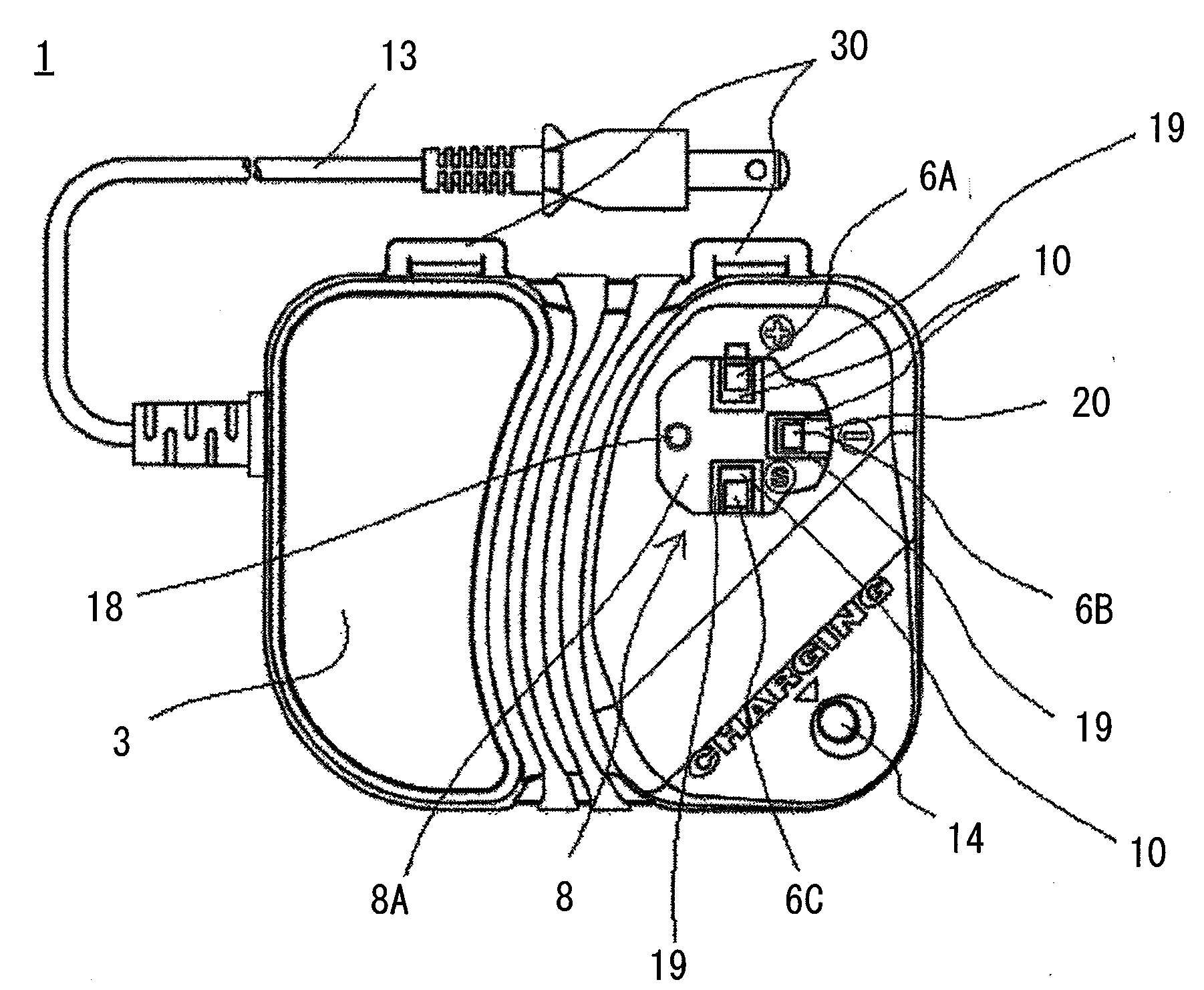
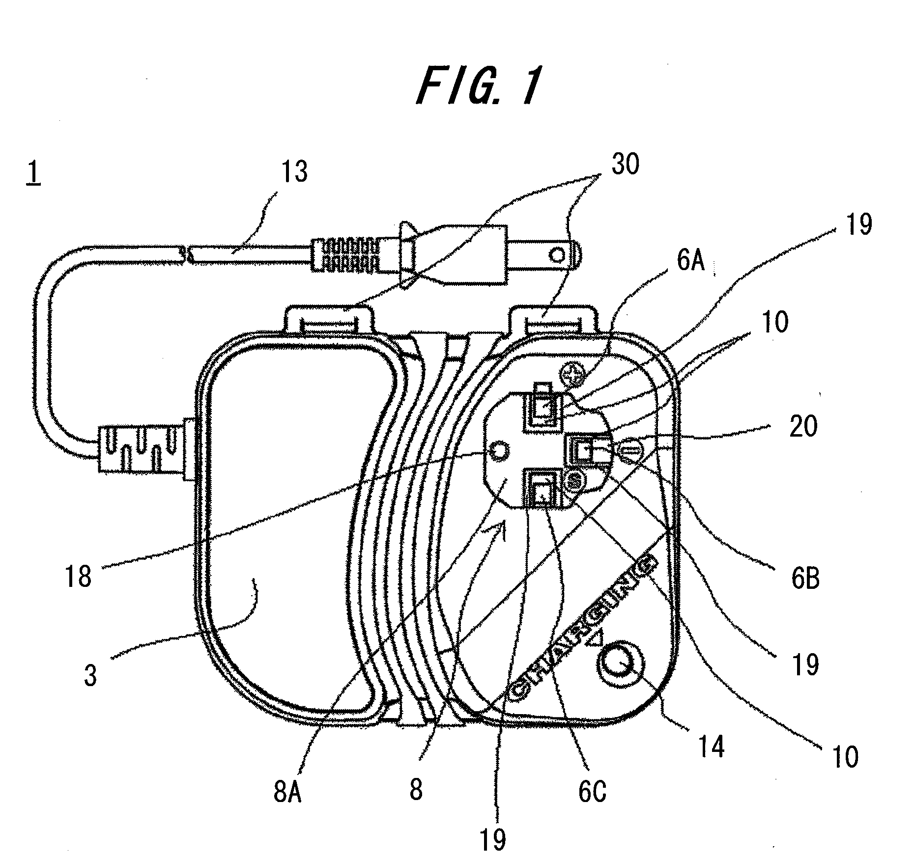
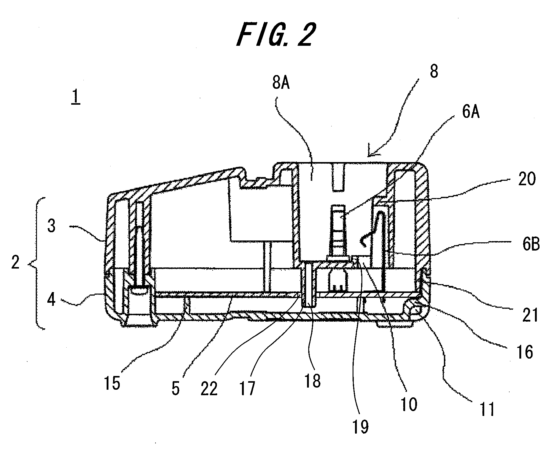
[0021]The battery charger 1 related to the embodiment of the present invention is described using FIGS. 1 to 3. FIG. 1 is a top view of the battery charger related to the embodiment of the present invention, FIG. 2 is a cross-sectional view of FIG. 1 and FIG. 3 is a view illustrating the situation when the battery pack is connected to the battery charger in FIG. 2.

[0022]The battery charger 1 is mainly configured of the battery connection portion 8 connecting to the battery pack 7, the top case 3 and the bottom case 4 to configure the body case 2, and the circuit substrate 5 mounted with a charging circuit to charge the battery pack 7. Electricity is supplied via the charging circuit from a power cord 13 to the charging terminal 6 described afterward to charge the battery pack 7 by contacting the charging terminal 6 with the charge and discharge terminal 9 of the battery pack 7 connected to the battery connection portion 8.

[0023]As described in more detail, as shown in FIG. 1 the bat...


PUM


Abstract

The problem of the present invention is to configure a battery charger such that water intruded into a gap between a plugging portion of a battery connection part in the battery charger and a battery pack does not contact the circuit substrate, with a simple and low-cost configuration, and improving recyclability of the circuit substrate. The battery charger is configured such that water intruded from the gap between the plugging portion of the battery connection portion and the battery pack, is guided through a through-hole of a protruded portion provided at the bottom of the plugging portion to the lower side of the circuit substrate provided on the bottom case.

Description

BACKGROUND OF THE INVENTION[0001]1. Field of the Invention[0002]The present invention relates to a battery charger to charge a battery pack.[0003]2. Description of the Related Art[0004]Configuration of a conventional battery charger is described using FIGS. 4 to 6. Battery charger 100 is configured by placing a circuit substrate 5, a charging terminal 6 and a signal terminal 6C in a body case 2 composed of a top case 3 and a bottom case 4. The top case 3 is provided with a battery connection portion 8 for connecting to a battery pack 7. The battery connection portion 8 is provided with a plugging portion (retention portion) 8A in order to retain the battery pack 7 when the battery pack 7 is inserted, and terminal insertion holes 10, through which the charging terminal 6 and the signal terminal 6C pass, are provided at the bottom of the plugging portion 8A. A charge and discharge terminal 9 of the battery pack 7 contacts the charging terminal 6 to charge the battery pack 7. On the ot...

Claims


Application Information

Patent Timeline
Patent Type & Authority Applications(United States)
IPC IPC(8): H02J7/00
CPCH02J7/0042H01M10/46Y02E60/10
Inventor MIZOGUCHI, TOSHIOFUJISAWA, HARUHISASAITOU, KEITA
Owner HITACHI KOKI CO LTD
Learn More