Radio frequency identification tag

a radio frequency identification and tag technology, applied in the field of rfid (radio frequency identification) tags, can solve the problems of inability to obtain desired communication distance, difficult to attach the rfid tag to all currently distributed disk media, and difficult to attach the balancer to a data storage area, etc., to achieve stable communication characteristics, reduce the amount of mass eccentricity due to the attachment of the rfid tag, and reduce the effect of mass eccentricity

Inactive Publication Date: 2009-04-02
HITACHI LTD
View PDF6 Cites 15 Cited by
  • Summary
  • Abstract
  • Description
  • Claims
  • Application Information

AI Technical Summary

Benefits of technology

[0007]The present invention has been devised in order to solve the above-described problems, and the amount of mass eccentricity due to the attachment of the RFID tag is reduced. Further, it is an object thereof to provide the RFID tag which does not depend on a structure of the disk medium and with which stable communication characteristics are obtained.
[0008]The RFID tag according to the present invention is devised in order to attain the above-described object. For that purpose, the RFID tag according to the present invention is an RFID tag having mounted thereon an IC chip capable of receiving and delivering information from and to an external source without contact. In the RFID tag, the central axis of the RFID tag is determined from the central axes of the IC chip, the antenna and the substrate, and the mass eccentricity is reduced by allowing the central axis of the RFID tag to coincide with the rotation axis of the disk medium.

Problems solved by technology

In the technology disclosed in U.S. Pat. No. 6,359,842 B1, it is also difficult to attach the RFID tags on all of the currently distributed disk media.
For example, in the DVD having recorded thereon data on both surfaces of the disk medium, it is difficult to attach the balancer on a data storage area as described in U.S. Pat. No. 6,359,842 B1.
Antenna characteristics change near the metal conductive layer and as a result, a desired communication distance cannot be obtained.
Further, when the RFID tag is attached on the metal conductive layer, the antenna characteristics largely change and the RFID tag does not function as a practical RFID tag in many cases.
However, when the RFID tag with the thick spacer is attached on the disk medium, the disk medium cannot be mounted on the disk drive in many cases, and therefore, the measures cannot be taken.

Method used


Image

  • Radio frequency identification tag
  • Radio frequency identification tag
  • Radio frequency identification tag

Examples


first embodiment

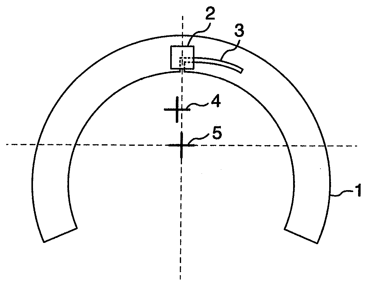
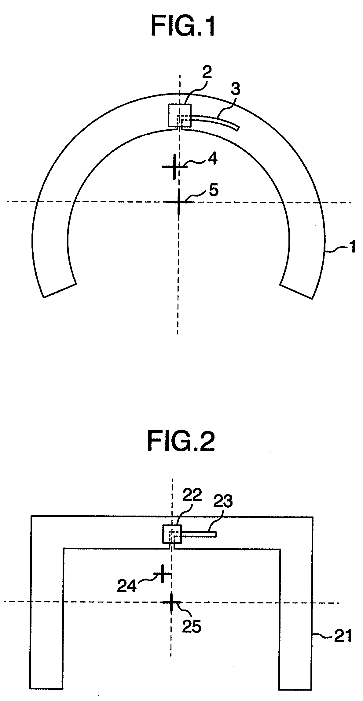
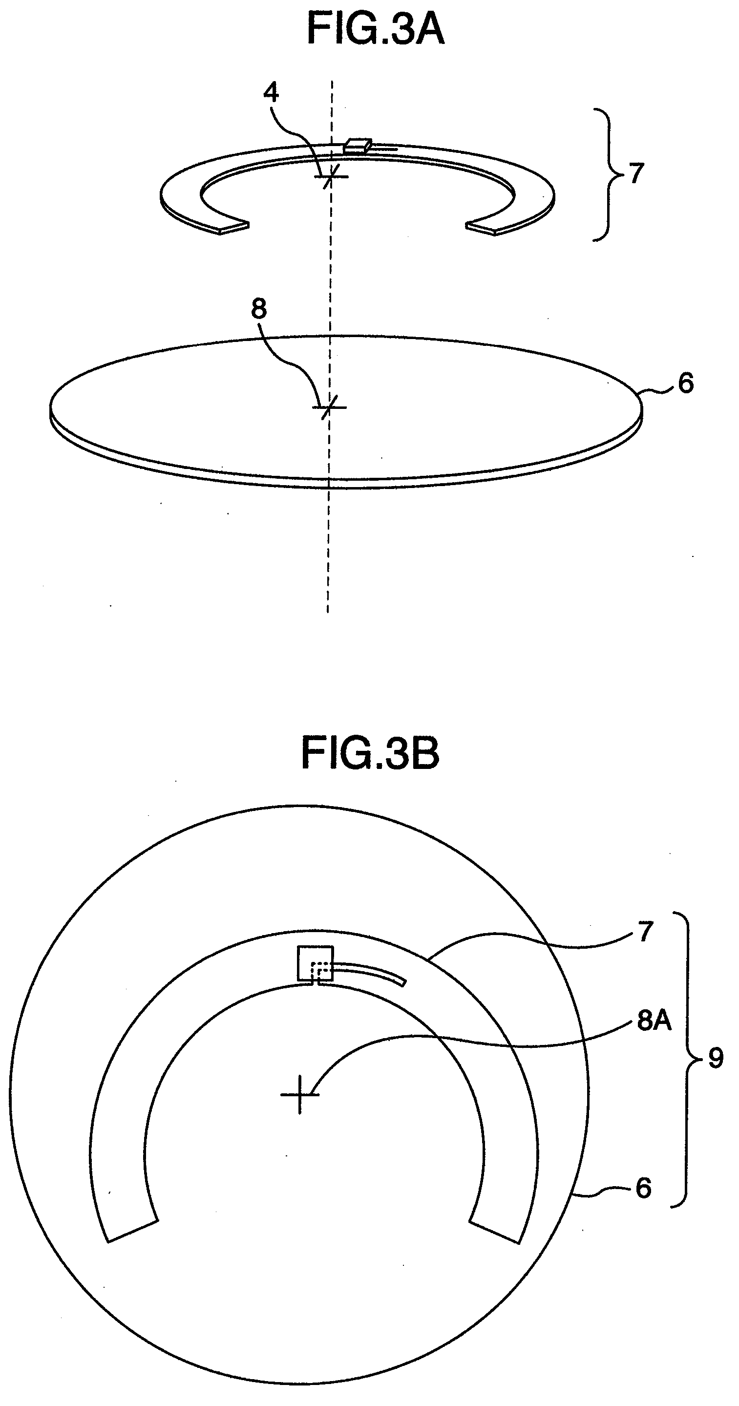
[0031]First, an RFID according to the first embodiment will be described with reference to FIG. 1. FIG. 1 shows an antenna of the circular RFID tag. On a circular antenna 1, an L-type slit 3 for performing impedance matching between an IC chip having recorded therein information and the antenna 1 is formed. The IC chip 2 having recorded therein information is mounted on this antenna 1. Description will be made later on the connection between the antenna 1 and the IC chip 2. There exists a center 5 being a center of a shape determined from a width and length of the antenna 1. A central axis of the antenna 1 having mounted thereon the IC chip 2 is located at a position shown in a central axis 4. When the antenna 1 is rotated around this central axis, a mass eccentricity can be canceled without using a balancer. The central axis used herein means an axis almost vertically penetrating an antenna surface via a center of gravity.

[0032]For measurement of the central axis, there is used a m...

second embodiment

[0042]The embodiment will be described on the case where the metal conductive layer 14B serving as a light reflecting film is formed up to the clamping area of the disk medium as described above. FIG. 8B shows a method of attaching the RFID tag on the disk medium 12B having a DVD structure and in which the metal conductive layer 14B is formed up to the clamping area. In the structure of FIG. 8B, the metal conductive layer 14B is formed in the clamping area R4 having attached thereon the RFID tag. Accordingly, even if the RFID tag 9A described in the first embodiment is attached on the clamping area R4, the RFID tag cannot sufficiently respond to signals outputted from a reader due to the effect of the metal conductive layer 14B. This phenomenon is the same as that in the case where a general-purpose RFID tag is attached on a metallic article. Therefore, the RFID tag can be operated by a method of inserting a spacer between the metal conductive layer and the RFID tag 9A. However, the...

third embodiment

[0053]The reading speed of the disk medium is increased and the number of rotations of the disk medium is increased and therefore, a reading error may be caused by vibrations due to the turbulence of air flow generated within the disk drive. In the present embodiment, with reference to FIG. 15, description will be made on a structure of the RFID tag for preventing the turbulence of air flow generated within the disk drive. The RFID tag described in the first and the second embodiments has a structure in which the IC chip is formed on the disk medium. However, the RFID tag has a shape in which the IC chip has a thickness of 50 μm and only the IC chip having a protrusion with a height of 50 μm is formed on the antenna. A protective film is formed on the tag antenna; however, the periphery of the IC chip is projected. When the disk medium rotates at high velocity, the turbulence of air flow is generated within the disk drive due to this protrusion and vibrations of the disk medium occu...


PUM


Abstract

An RFID tag having mounted thereon an IC chip capable of receiving and delivering information from and to an external source without contact. In the RFID tag, a central axis of its own antenna having mounted thereon the IC chip coincides with a center of the RFID tag, and an antenna width is controlled. That is, a position of the central axis of the antenna is controlled to correct the mass eccentricity of the RFID tag. Further, the RFID tag is an RFID tag having mounted thereon the IC chip capable of receiving and delivering information from and to an external source without contact, and an RFID tag having attached thereon the IC chip at a position in which a first and a second antenna lengths are different from each other.

Description

INCORPORATION BY REFERENCE[0001]The present application claims priority from Japanese application JP2007-253027 filed on Sep. 28, 2007, the content of which is hereby incorporated by reference into this application.BACKGROUND OF THE INVENTION[0002]The present invention relates to an RFID (Radio Frequency Identification) tag for wirelessly transmitting information such as ID (Identification) recorded in an IC chip.[0003]An RFID tag comprises an IC chip and an antenna and can wirelessly transmit information such as an ID number recorded in the IC chip from the antenna. Accordingly, when communicating with the RFID tag using a reader / writer, information recorded in the IC chip can be read without contact. Thanks to radio transmission, information on IC chips can be read even in articles stored in a bag or box. Therefore, the RFID tag is widely used for manufacturing management and logistics of articles. In the management, the management of CD (Compact Disk), being an optical disk for u...

Claims


Application Information

Patent Timeline
Patent Type & Authority Applications(United States)
IPC IPC(8): G08B13/14G11B7/24G11B7/24094
CPCG06K19/04G06K19/045G11B23/0042G11B20/00876G11B20/00086G06K19/07G11B23/30
Inventor SAKAMA, ISAOHESAKI, SHIMPEIKUDO, NOBUHIRO
Owner HITACHI LTD
Why Eureka
Try Eureka