Capping unit and ink jet recording unit

a technology of ink jet and recording unit, which is applied in printing and other directions, can solve the problems of ejection defect, leakage of distribution ink from ejection outlets, and occurrence of deformation or the like in an area, and achieve the effect of reducing the impa

Active Publication Date: 2009-04-02
CANON KK
View PDF11 Cites 3 Cited by
  • Summary
  • Abstract
  • Description
  • Claims
  • Application Information

AI Technical Summary

Benefits of technology

[0020]By employing such a constitution, even in the case where a recording head accidentally falls so as to have impact on an ejection outlet-formed surface provided with ejection outlets, the elastic portion is elastically deformed to alleviate the impact.

Problems solved by technology

Due to such non-uniform wettability with respect to the ink, ejection defect can occur.
In such cases, there is a possibility of leakage of the distribution ink from the ejection outlets or the ink introducing port.
However, when the recording element substrate is pressed under such a strong pressure, there is a possibility of an occurrence of deformation or the like in an area, in which the ejection outlets are formed, of the recording element substrate.
Further, dust or contaminant can enter between the recording element substrate and the tape or the rubber material, so that there is a possibility of clogging of the ejection outlets with heat dust or contaminant.
In addition, an adhesive on the tape surface is transferred onto the recording element substrate, so that there is a possibility of a change in wettability of the recording element substrate with respect to the ink or a possibility of an occurrence of damage on the recording element substrate.
When the capping unit is removed in this state, the droplet of the distribution ink deposited on the ejection outlet surface drips, so that there is possibility of contamination of user's hand or clothes, a work-bench, or the like with the dripped distribution ink.
When the spacing is excessively large, the distribution ink grows into the large droplet as described above, so that the droplet of the distribution ink drips when the capping unit is removed.
On the other hand, when the spacing is excessively small, due to impact during recording head falling, the ejection outlet-formed area and the liquid-absorbing member contact each other.
For that reason, it is necessary that a dimension of the liquid-absorbing member is strictly regulated, that an impact-absorbing material (rubber material) is used, and that a complicated structure is formed, so that there arose problems in terms of design latitude, ecology, and cost.
In the case where the liquid-absorbing member contacts the ejection outlet-formed area due to the impact during the recording head falling, there is a possibility of an occurrence of damage such as deformation of the ejection outlets.
Further, in the case where the liquid-absorbing member contacts a portion of the ejection outlet surface other than the ejection outlet-formed area so that the liquid-absorbing member does not contact the ejection outlet-formed area, there is a possibility of an occurrence of damage of the ejection outlet surface by the falling impact.
In order to alleviate such impact during the falling of the recording head, it is possible to employ a method in which a large amount of a cushioning member is put in the capping unit or the recording head is put in a strict packing material but the method involves a problem of an increase in cost, so that an increase in packing member is undesirable also from an ecological viewpoint.

Method used


Image

  • Capping unit and ink jet recording unit
  • Capping unit and ink jet recording unit
  • Capping unit and ink jet recording unit

Examples


Embodiment Construction

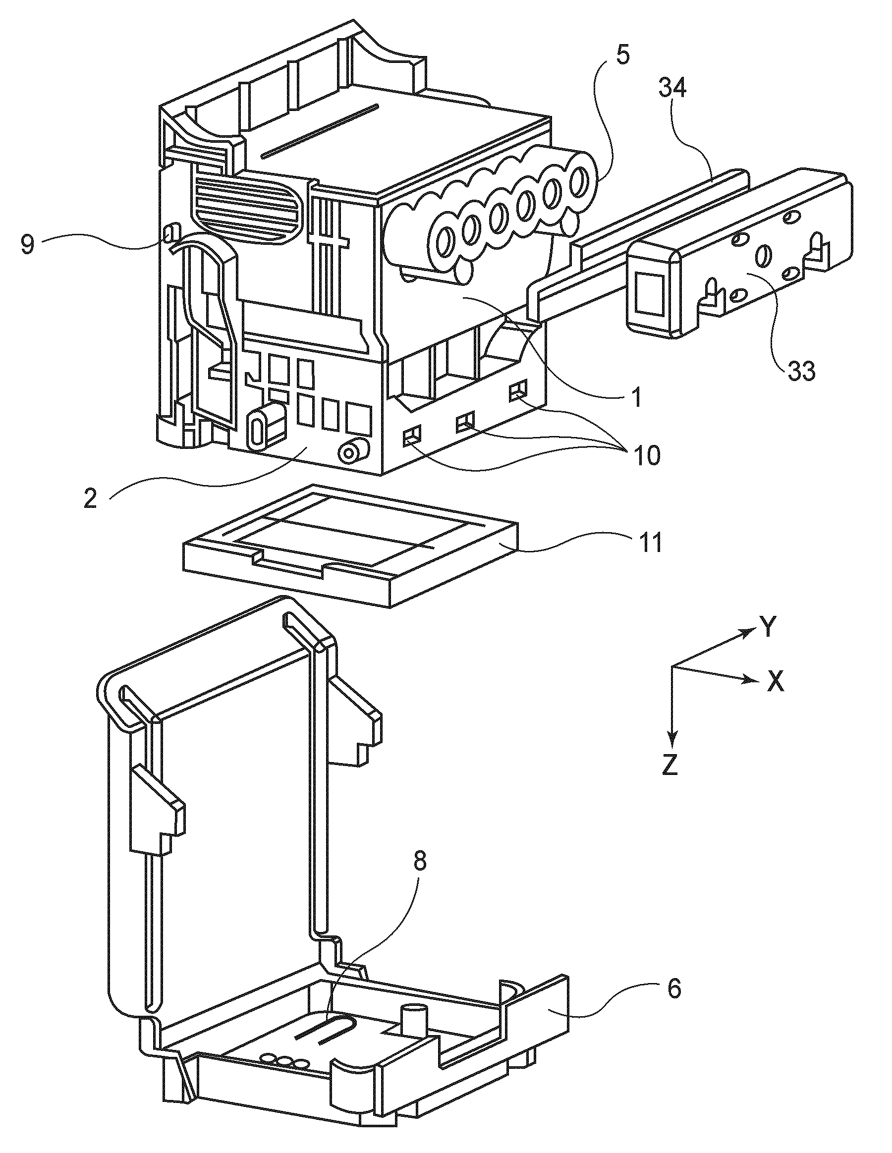
[0031]A constitution of a capping unit to which the present invention is applied will be described with reference to the drawings.

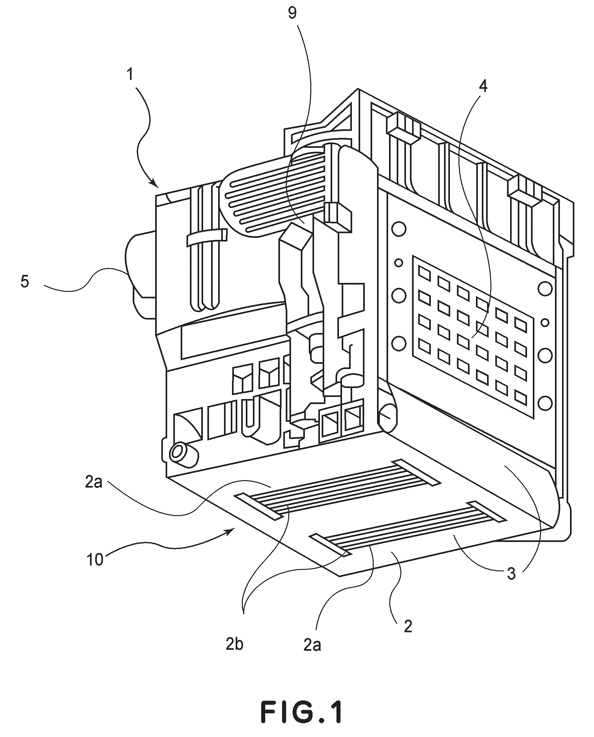
[0032]FIG. 1 is a perspective view schematically showing an ink jet recording head 1 to which the capping unit according to the present invention is to be mounted. Referring to FIG. 1, the recording head 1 includes an ejection outlet surface 2 provided with ejection outlets 2b for ejecting ink, a recording element substrate 2a on which the ejection outlets 2b and a recording element (not shown) for ejecting ink from the ejection outlets 2b are formed, a connecting contact 4 for electrically connecting the recording head 1 to an ink jet recording apparatus, an electric wiring tape 3 for electrically connecting the recording element substrate 2a and the connecting contact 4, and an ink injection port 5 into which an ink supply tube (not shown) for supplying ink from an ink container (not shown) is to be inserted and connected. The ink supplied from the ink ...


PUM


Abstract

A capping unit is detachably mountable to an ink jet recording head. The ink jet recording head has an ejection outlet surface provided with ejection outlets for ejecting ink. The capping unit includes: a liquid-absorbing member provided with a projection contactable to a periphery of an area, in which the ejection outlets are formed, on the ejection outlet surface so as to form a gap between the area and the liquid-absorbing chamber; and a capping member including an engaging portion and an elastic portion for contacting a rear surface opposite from a surface on which the projection of said liquid-absorbing member is formed to press said liquid-absorbing member against the ejection outlet surface.

Description

FIELD OF THE INVENTION AND RELATED ART[0001]The present invention relates to a capping unit for protecting, during distribution, an ink jet recording head for effecting recording by ejecting a recording head from ejection outlets.[0002]As an example of a structure of a recording apparatus using an ink jet technology, a recording apparatus disclosed in U.S. Pat. No. 6,805,437 has been known.[0003]In the recording apparatus disclosed in U.S. Pat. No. 6,805,437, ink is supplied from a main container to an ink jet recording head by a so-called tube supply method. This recording head includes a recording element substrate provided with nozzles (constituted by ejection outlets and flow passages communicating with the ejection outlets) for ejecting the ink, an ink retaining space, and an ink introducing port. Further, in order not to cause ejection defect due to an abrupt change in pressure and leakage of ink from the ejection outlets and the ink introducing port, buffer portions such as a...

Claims


Application Information

Patent Timeline
Patent Type & Authority Applications(United States)
IPC IPC(8): B41J2/165
CPCB41J2/16505B41J2/1752B41J2/17553B41J2/17533B41J2/1753
Inventor ISHIMATSU, SHINKITABATAKE, KENJIKOIZUMI, YUTAKA
Owner CANON KK
Why Eureka
Try Eureka