Feedback drive for resonant oscillation of scanner mechanism

a scanner mechanism and resonant oscillation technology, applied in the direction of instruments, optical elements, discharge tubes/lamp details, etc., can solve the problems of large power requirement, increased driving energy, damp oscillation,

Inactive Publication Date: 2009-04-02
METROLOGIC INSTR
View PDF2 Cites 10 Cited by
  • Summary
  • Abstract
  • Description
  • Claims
  • Application Information

AI Technical Summary

Problems solved by technology

But, a larger amount of power is necessary if the mechanical parts are forced to conform to the phase and frequency of a driver at an arbitrary frequency.
However, this is a challenge because the natural oscillation frequency varies somewhat from one device to another within normal manufacturing variations and tolerances.
Applying force at an inaccurate phase position can damp oscillation, render oscillation unstable or require more driving energy than might be necessary to sustain natural oscillation.

Method used


Image

  • Feedback drive for resonant oscillation of scanner mechanism
  • Feedback drive for resonant oscillation of scanner mechanism
  • Feedback drive for resonant oscillation of scanner mechanism

Examples


Embodiment Construction

[0021]This description of the exemplary embodiments is intended to be read in connection with the accompanying drawings, which are to be considered part of the entire written description. In this description, certain relative terms are employed from time to time to describe relative positions or directions. Examples are “lower,”“upper,”“horizontal,”“vertical,”, “above,”“below,” etc. These terms are used to refer for convenience in referring to the orientations and relative positions in the examples as then described or as shown, and should not be construed to require that the apparatus be constructed or operated in any particular orientation. Terms concerning attachments, coupling and the like, such as “connected” and “interconnected,” are used herein to describe relationships wherein structures are secured or attached to one another either directly or indirectly through intervening structures, and should be construed to encompass either movable or rigid connections, attachments or ...


PUM


Abstract

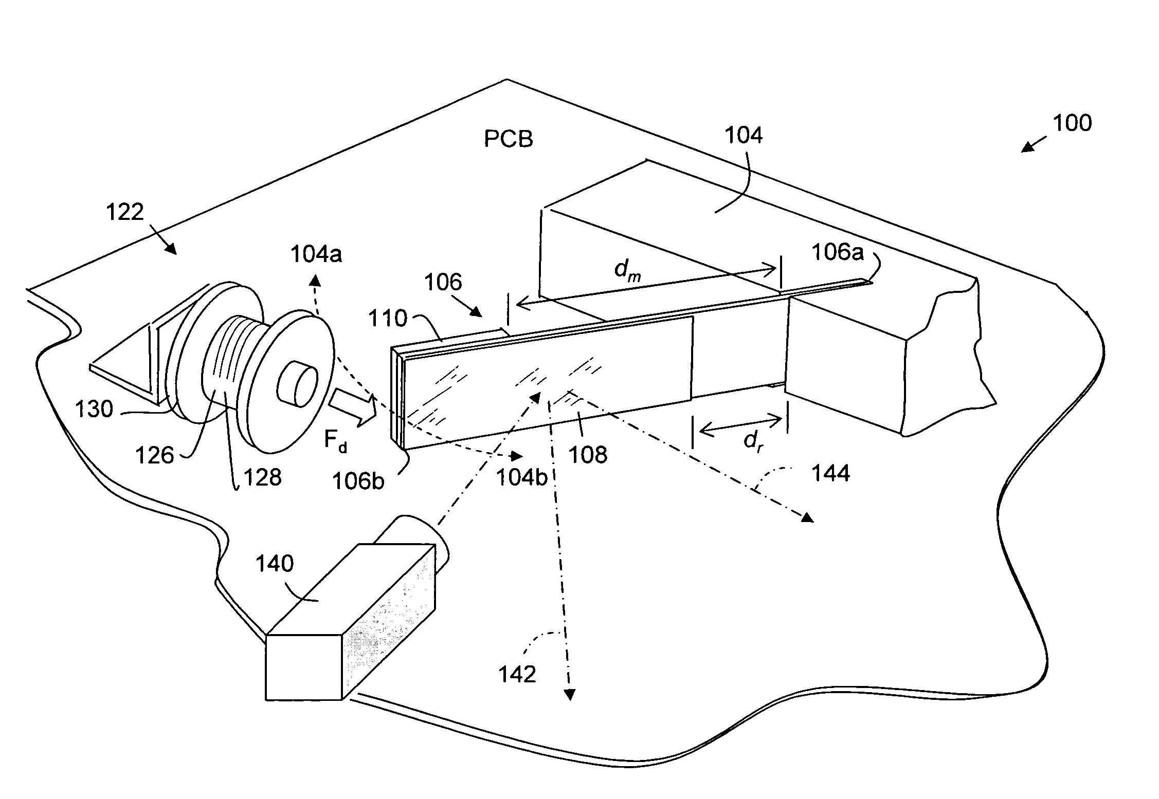
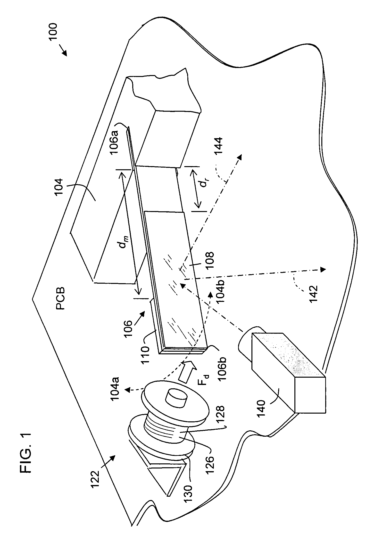
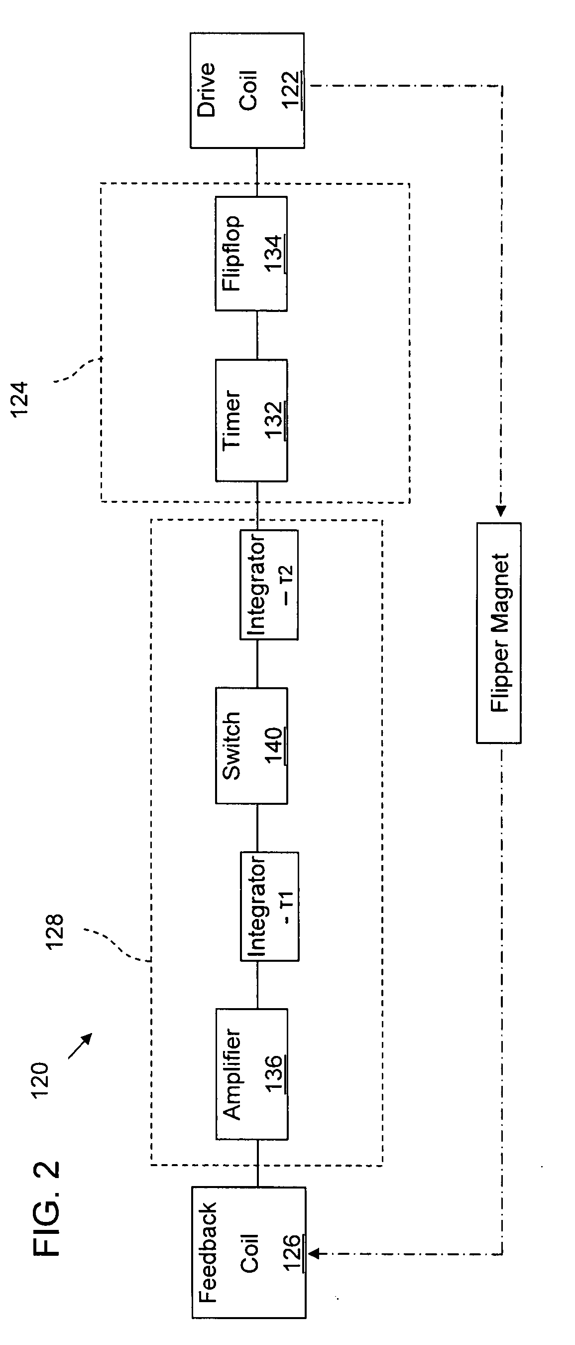
A drive for oscillating a reflector in a beam scanner, and for other similar oscillating devices, forms a feedback loop synchronized to the natural resonance of a resiliently movable flipper strip carrying the reflector. A magnet on the free end of the flipper generates a current in a sensing coil coupled to an amplifier upon passage of the magnet. The triggering signal is phase delayed by one or more integrators or timers, whereupon a driving current is generated, for example in a different winding on the same spool as the sensing coil. The driving current is applied at a phase delay that maintains oscillation up to a high operational frequency in a range. Synchronizing the drive to the natural frequency and phase of the flipper substantially reduces power consumption compared to forcing oscillation to a different reference.

Description

FIELD OF THE INVENTION[0001]The invention relates to driving electromechanical oscillating mechanisms. The position of a resiliently movable element in its oscillating cycle is sensed in a feedback loop that triggers drive pulses phased to maintain oscillation. The result is oscillation near the natural mechanical resonance of the device, at low power consumption. The technique is applied to driving a resilient flipper carrying a reflector used to scan the illuminating beam of a barcode reader.PRIOR ART[0002]Electromechanical oscillating devices have various applications, one being to position a reflector or other movable part when repetitively scanning a point back and forth over an optical scan line. In one type of optical beam scanner that is useful for example in a barcode reader, a laser beam is incident on a reflector carried on a resilient film that is fixed along a line at one end, defining a resilient hinging axis. A magnet or coil on the substrate is spaced from the hingin...

Claims


Application Information

Patent Timeline
Patent Type & Authority Applications(United States)
IPC IPC(8): G02B26/08
CPCG06K7/10653G02B26/105
Inventor BLAKE, ROBERT E.
Owner METROLOGIC INSTR
Why Eureka
Try Eureka