Aerodynamic LED Floodlight Fixture

a floodlight fixture and led technology, applied in the field of floodlight fixtures, can solve the problems of heat dissipation, the goal of heat dissipation and protection of electronic led drivers can often be conflicting, and the fixture development is difficul

Inactive Publication Date: 2009-04-02
RUUD LIGHTING
View PDF99 Cites 39 Cited by
  • Summary
  • Abstract
  • Description
  • Claims
  • Application Information

AI Technical Summary

Benefits of technology

[0010]Another object of the invention is to provide an improved LED floodlight fixture that is readily adaptable for a variety of mounting positions and situations.
[0011]Another object of the invention is to provide an improved LED floodlight that reduces development and manufacturing costs for LED floodlight for different floodlight applications.
[0012]Another object of the invention is to provide an improved LED floodlight with aerodynamic properties subjecting it to less wind load when mounted on a pole or similar mounting.
[0024]In certain preferred embodiments the frame structure preferably includes a vent permitting air flow to and from the LED assembly. Such venting facilitates cooling the LED assembly.

Problems solved by technology

Floodlights using LED modules as light source for various applications present particularly challenging problems in fixture development, particularly when floodlight mounting locations and structures will vary.
Heat dissipation is another problem for LED floodlights.
And, the goals of dealing with heat dissipation and protection of electronic LED drivers can often be conflicting, contrary goals.
Wind load is another problem for LED floodlights and floodlights that are mounted on poles in general.
Some LED floodlights of the prior art are bulky in size.
Given their bulky nature these floodlights are very susceptible to wind load damage.

Method used


Image

  • Aerodynamic LED Floodlight Fixture
  • Aerodynamic LED Floodlight Fixture
  • Aerodynamic LED Floodlight Fixture

Examples


Embodiment Construction

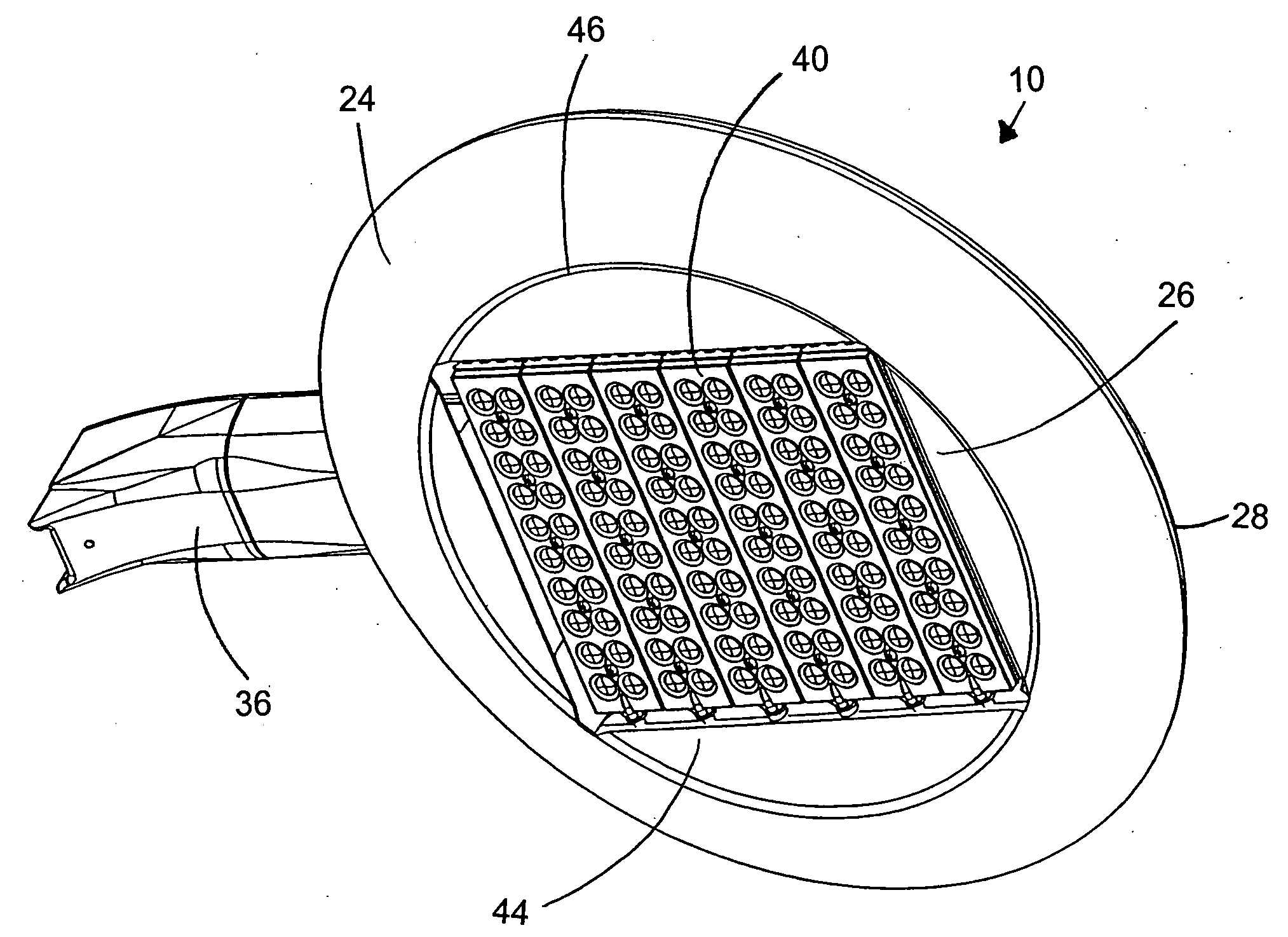
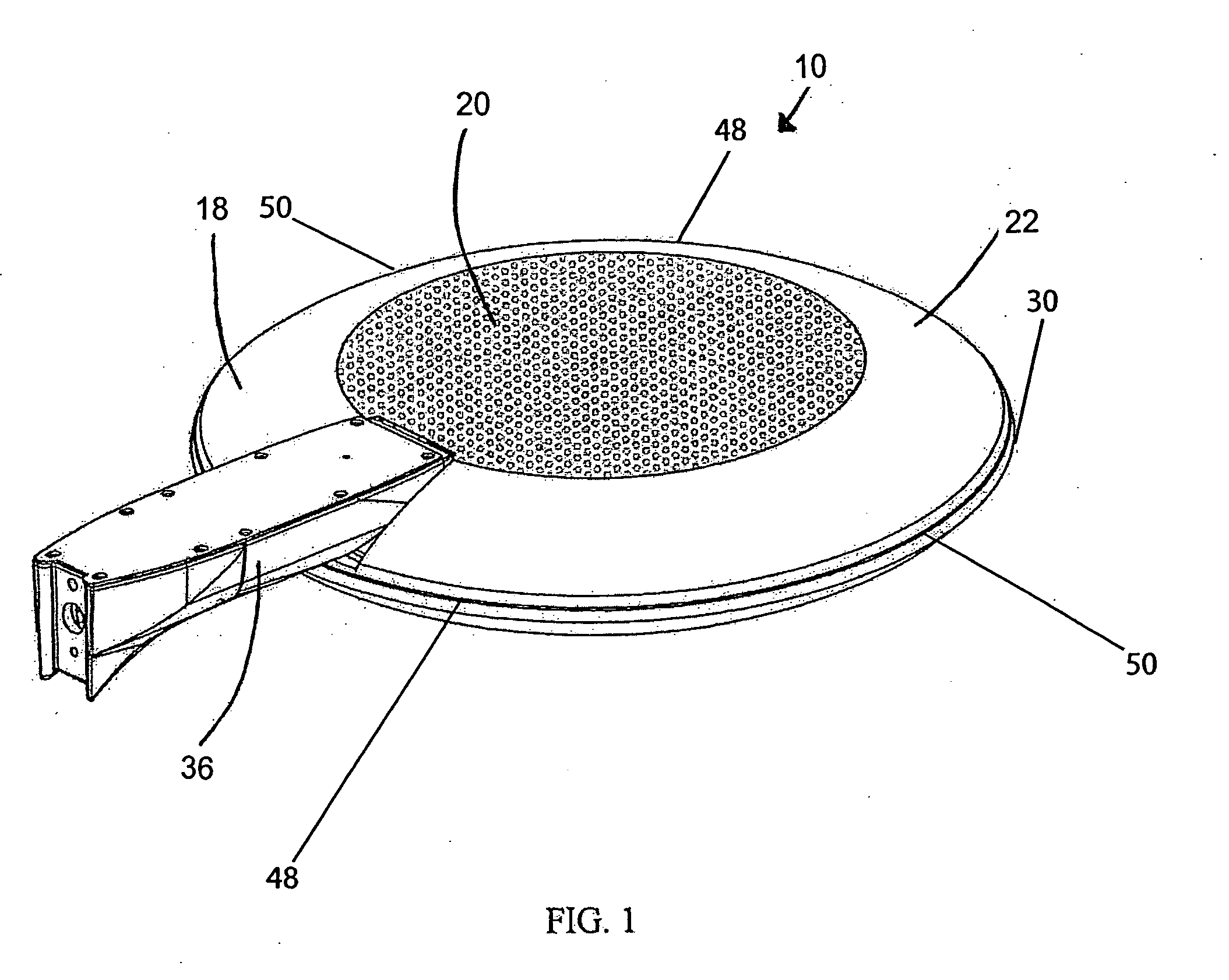
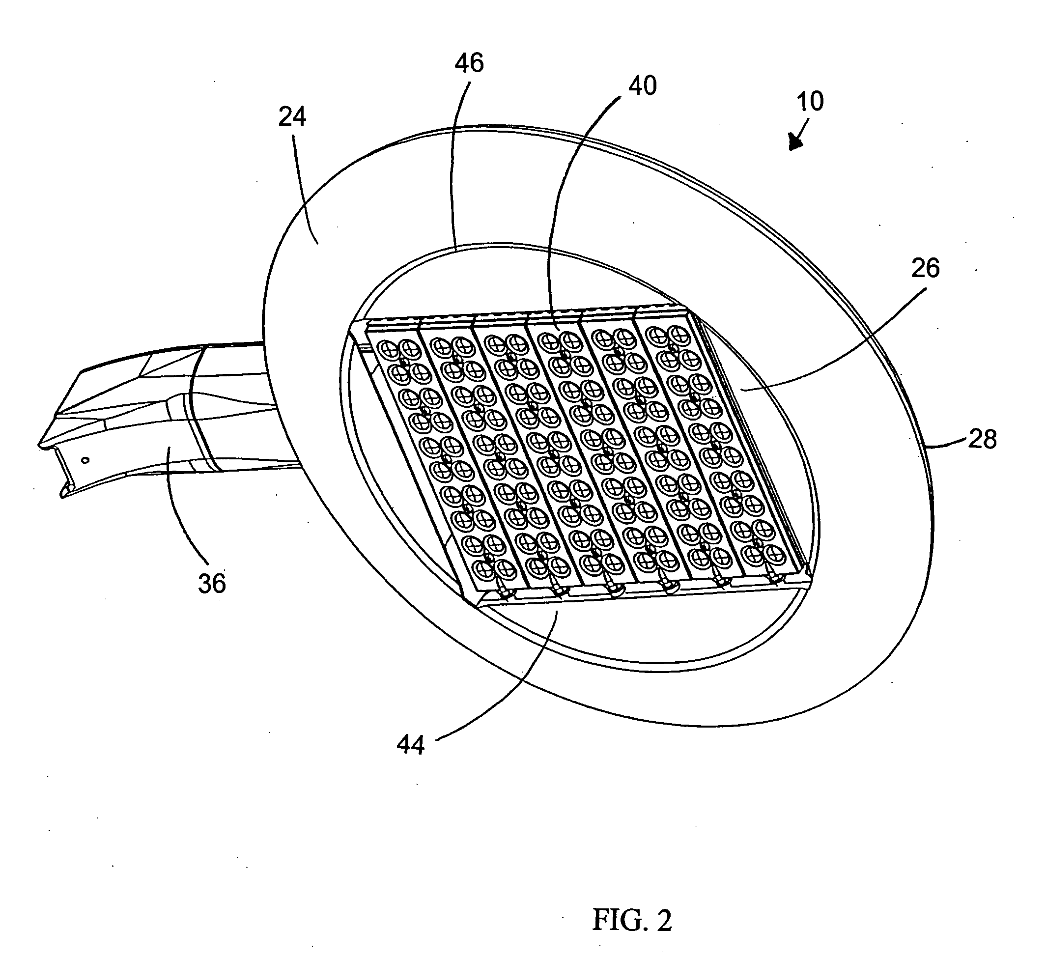
[0055]FIGS. 1-4 illustrate a preferred LED floodlight fixture in accordance with this invention. LED floodlight fixture 10 includes two major principal axes (illustrated in FIGS. 5-7 as 1, 2) in a fixture plane 42 (illustrated in FIG. 3). The dimensions parallel to its third principal axis (illustrated in FIGS. 7 and 8 as 3) are substantially smaller than the largest dimensions parallel to fixture plane 42. A simple graphical explanation of the three principal axes (1-3) is shown in FIGS. 5-7.

[0056]As best seen in FIGS. 1-3, fixture 10 is characterized by a first outer surface IS having a first central portion 20 and a first edge-adjacent portion 22, an opposite second outer surface 24 having a second central portion 44 substantially aligned with first central portion 20 and encompassing a light-emitting region 26 and a second edge-adjacent portion 28 having a boundary 46. Second central portion 44 also includes second edge-adjacent portion 28 having a boundary 46 with second centra...


PUM


Abstract

An LED floodlight fixture having two major principal axes in a fixture plane, the dimensions parallel to the fixtures third principal axis being substantially smaller than the largest dimensions parallel to the fixture plane. The fixture is characterized by a first outer surface which has a first central portion and a first edge-adjacent portion, an opposite second outer surface which has a second central portion substantially aligned with the first central portion and encompassing a light-emitting region and a second edge-adjacent portion having a boundary with the second central portion such boundary defining a reference plane, the first and second edge-adjacent portions meet at a perimetrical edge. The first and second central portions each extend across at least 25% of the area within the perimetrical edge. The first and second edge-adjacent portions form aerodynamic-drag-reducing cross-sectional profiles transverse to the fixture plane and extend in substantially all in-fixture plane directions, the greatest dimension between the first central portion and the reference plane is no more than 50% greater than the smallest dimension therebetween.

Description

FIELD OF THE INVENTION[0001]This invention relates to lighting fixtures and, more particularly, to floodlight fixtures using LED modules.BACKGROUND OF THE INVENTION[0002]In recent years, the use of light-emitting diodes (LEDs) for various common lighting purposes has increased, and this trend has accelerated as advances have been made in LEDs and in LED arrays, often referred to as “LED modules.” Indeed, lighting applications which previously had been served by fixtures using what are known as high-intensity discharge (HID) lamps are now beginning to be served by fixtures using LED-array-bearing modules. Such lighting applications include, among a good many others, roadway lighting, factory lighting, parking lot lighting and commercial building lighting.[0003]Work continues in the field of LED module development, and also in the field of using LED modules for various lighting fixtures in various applications. It is the latter field to which this invention relates.[0004]Floodlights u...

Claims


Application Information

Patent Timeline
Patent Type & Authority Applications(United States)
IPC IPC(8): F21V15/01F21V29/00
CPCF21S2/005F21S8/086F21V15/01F21W2131/103F21V29/70F21Y2105/001F21K9/00F21S8/043F21V29/004F21Y2101/02F21Y2105/10F21Y2115/10
Inventor RUUD, ALAN J.WILCOX, KURT S.WALCZAK, STEVEN R.
Owner RUUD LIGHTING
Why Eureka
Try Eureka