Image Reading Apparatus and Image Reading Method

Inactive Publication Date: 2009-04-02
MITSUMI ELECTRIC CO LTD
View PDF5 Cites 9 Cited by
  • Summary
  • Abstract
  • Description
  • Claims
  • Application Information

AI Technical Summary

Benefits of technology

[0014]An aspect of the present invention is directed to providing an image reading apparatus with a simple structure that is configured to set the light accumulating time of an image capturing device during normal image reading operations and is capable of acquiring a c

Problems solved by technology

However, in the case of using the conventional image reading apparatus as is described above in relation to FIGS. 1A-1C, when a fingerprint image is acquired under an environment where disturbance light is relatively strong, such as under direct sunlight, too much light may be accumulated at the fingerprint sensor 130 so that its pixel data output may be saturated and the ridges and valleys of the fingerprint in the resulting fingerprint image may not be easily distinguished.
In such a case, the acquired fingerprint image may not be suitably used for finger

Method used


Image

  • Image Reading Apparatus and Image Reading Method
  • Image Reading Apparatus and Image Reading Method
  • Image Reading Apparatus and Image Reading Method

Examples


Example

[0040]In the following, preferred embodiments of the present invention are described with reference to the accompanying drawings.

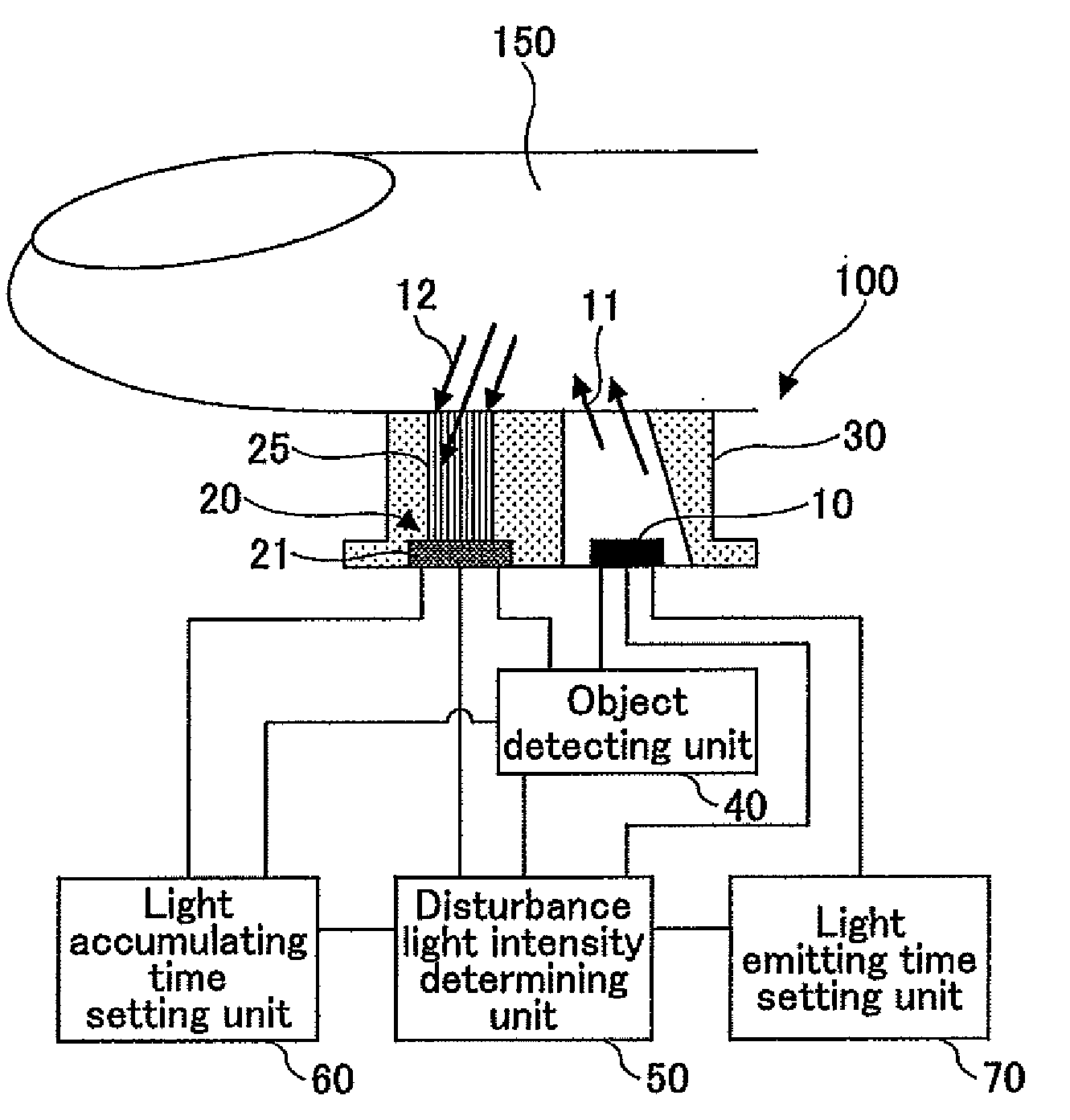
[0041]FIG. 3 is a diagram showing an image reading apparatus 100 according to an embodiment of the present invention. The image reading apparatus 100 illustrated in FIG. 3 includes a light emitting unit 10, an image capturing device 20, an object detecting unit 40, a disturbance light intensity determining unit 50, and a light accumulating time setting unit 60. Also, the image reading apparatus 100 may include an image guide 25, a housing 30, and / or a light emitting time setting unit 70, as is necessary or desired.

[0042]The light emitting unit 10 is configured to illuminate light on an object 150. The light emitting unit 10 may use an infrared LED (light emitting diode) or some other type of LED or light illuminating device. In the case where the light emitting unit 10 uses the infrared LED, it may be configured to emit infrared rays on the object 150, for...


PUM


Abstract

An image reading apparatus is disclosed that includes a light emitting unit that illuminates light on an object; an image capturing device that receives incident light from the object and generates an electrical signal according to the intensity of the received incident light; an object detecting unit that detects the object being positioned close to the image capturing device; a disturbance light intensity determining unit that turns off the light emitting unit when the object detecting unit detects the object being positioned close to the image capturing device, controls the image capturing device to acquire pixel data of a predetermined number of pixels by imaging the object, and determines a disturbance light intensity based on the acquired pixel data; and a light accumulating time setting unit that sets a light accumulating time of the image capturing device based on the disturbance light intensity determined by the disturbance light intensity determining unit.

Description

BACKGROUND OF THE INVENTION[0001]1. Field of the Invention[0002]The present invention relates to an image reading apparatus having a light emitting unit that is configured to read an image of an object according to the intensity of light reflected from the object. The present invention also relates to an image reading method.[0003]2. Description of the Related Art[0004]An image reading apparatus that reads a fingerprint image of a finger swiped over a linear fingerprint sensor in a substantially perpendicular direction with respect to the length direction of the fingerprint sensor is known. In such an image reading apparatus, the fingerprint sensor uses an image capturing device that is configured to receive light and output an electrical signal according to the intensity of the received light. Such an image capturing device is configured to acquire a fingerprint image in accordance with a predetermined light accumulating time when a finger is detected to be close to or in contact w...

Claims


Application Information

Patent Timeline
IPC IPC(8): G06K9/00H04N1/04G06V40/145A61B5/117G06T1/00H04N1/028H04N1/19
CPCG06V40/1341G06V40/14G06V40/145
Inventor MIZUSHIMA, SATOSHITAHARA, YOSHINORI
Owner MITSUMI ELECTRIC CO LTD
Why Eureka
Try Eureka