Image encoding apparatus and method for the same and image decoding apparatus and method for the same
- Summary
- Abstract
- Description
- Claims
- Application Information
AI Technical Summary
Benefits of technology
Problems solved by technology
Method used
Image
Examples
first embodiment
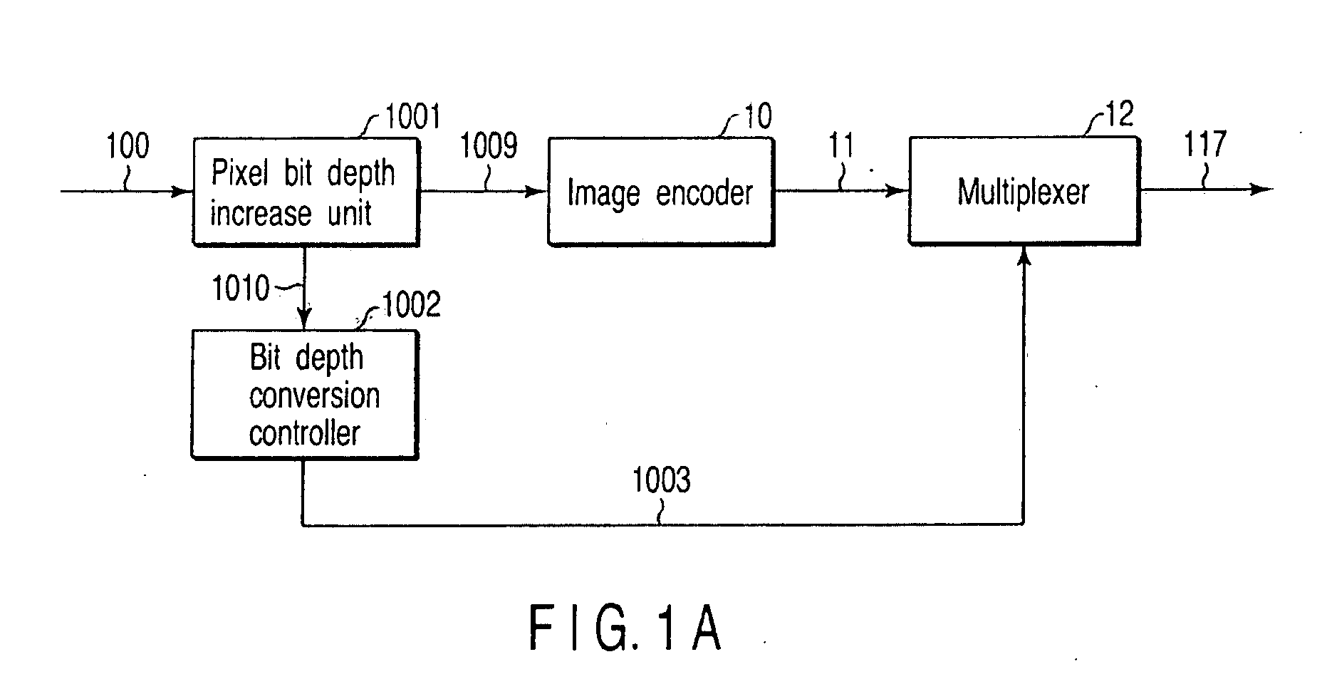
[0077]There will be described a configuration of an image encoding apparatus for video encoding according to the first embodiment referring to FIG. 1A. This image encoding apparatus comprises a pixel bit depth increase unit 1001 to which an input image signal 100 is supplied to increase a pixel bit depth (i.e., a pixel bit depth converter for changing pixel bit depth), an image encoder 10 connected to the output of this pixel bit depth increase unit 1001, a multiplexer 12 connected to the output of this image encoder 10, and a bit depth conversion controller 1002 connected to the other output of the pixel bit depth increase unit 1001 to supply bit depth increase information to the multiplexer 12.
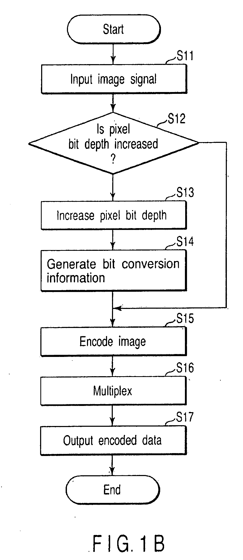
[0078]There will now be described an operation of the image encoding apparatus with reference to the flow chart of FIG. 1B. A video signal is input to this image encoding apparatus as an input image signal 100, for example, in units of one frame (S11). The pixel bit depth increase unit 1001 ...
second embodiment
[0119]There will be described configuration of an image encoding apparatus for video encoding related to the second embodiment referring to FIG. 9A. As shown in FIG. 9, this image encoding apparatus comprises a pixel bit depth increase unit (pixel bit depth converter) 1001, a bit depth conversion controller (bit depth conversion controller) 1002, a subtracter 101, an orthogonal transformer 104, a quantizer 106, a dequantizer 109, an inverse orthogonal transformer 110, an adder 111, a loop filter 113, a frame memory 114, a prediction image generator 115, and an entropy encoder 108. The output of the pixel bit depth increase unit 1001 receiving an input image signal is connected to the entropy encoder 108 through the subtracter 101, orthogonal transformer 104 and the quantizer 106. The output of quantizer 106 connected to the prediction image generator 115 through the dequantizer 109, the inverse orthogonal transformer 110, the adder 111, the loop filter 113, and the frame memory 114....
third embodiment
[0132]Configuration of the image encoding apparatus for video encoding according to the third embodiment of the present invention is shown in FIG. 11A. This image encoding apparatus is a configuration approximately similar to the configuration example shown in the second embodiment (FIG. 9), but differs from the second embodiment in the points of providing the pixel bit depth converter 1005 on the previous stage of the frame memory 114 and the pixel bit depth converter (pixel bit depth converter) 1006 on the rear stage of the frame memory 114.
[0133]There will now be described an operation of this image encoding apparatus with reference to FIG. 11B. A video signal is input to this image encoding apparatus as the image signal 100 in units of a frame, for example (S51). The pixel bit depth increase unit (pixel bit depth converter) 1001 does processing for increasing a value of each pixel of the input image signal 100 of N bit depth to (N+M) bit depth larger than N bits by M bits (S52)....
PUM
 Abstract
Description
Claims
Application Information
 - R&D
- Intellectual Property
- Life Sciences
- Materials
- Tech Scout
- Unparalleled Data Quality
- Higher Quality Content
- 60% Fewer Hallucinations
Browse by: Latest US Patents, China's latest patents, Technical Efficacy Thesaurus, Application Domain, Technology Topic, Popular Technical Reports.
© 2025 PatSnap. All rights reserved.Legal|Privacy policy|Modern Slavery Act Transparency Statement|Sitemap|About US| Contact US: help@patsnap.com


