
System and method for displaying images

Active Publication Date: 2007-08-30
TEXAS INSTR INC
View PDF5 Cites 15 Cited by
  • Summary
  • Abstract
  • Description
  • Claims
  • Application Information

AI Technical Summary

Benefits of technology

[0010] These and other problems are generally solved or circumvented, and technical advantages are generally achieved, by preferred embodiments of the present invention which provides a system and a method for enhancing image quality in a display system.
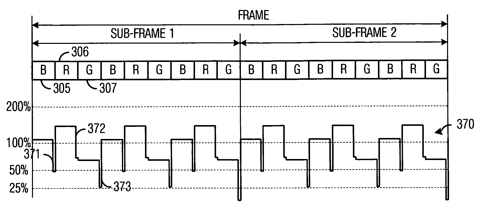
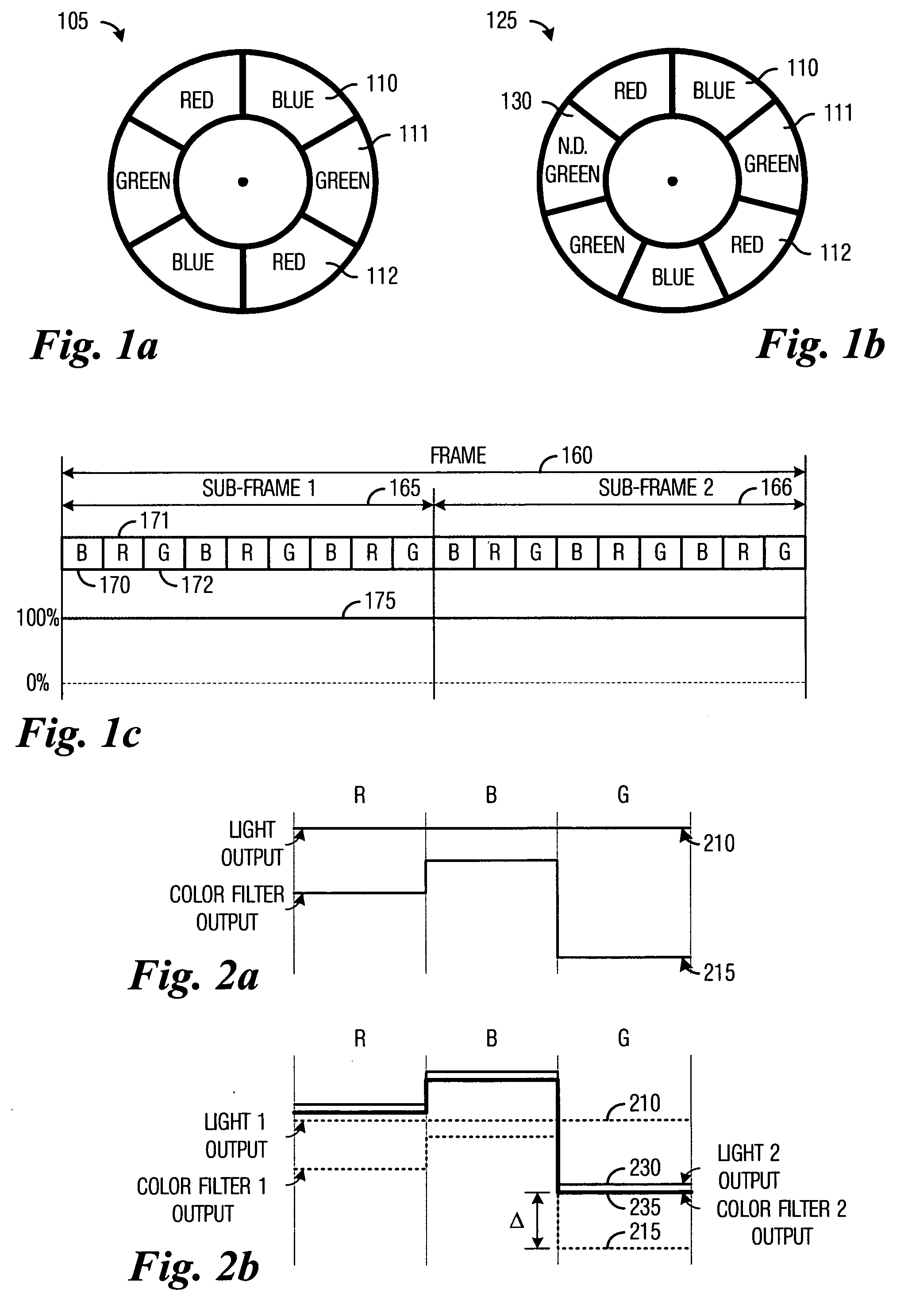
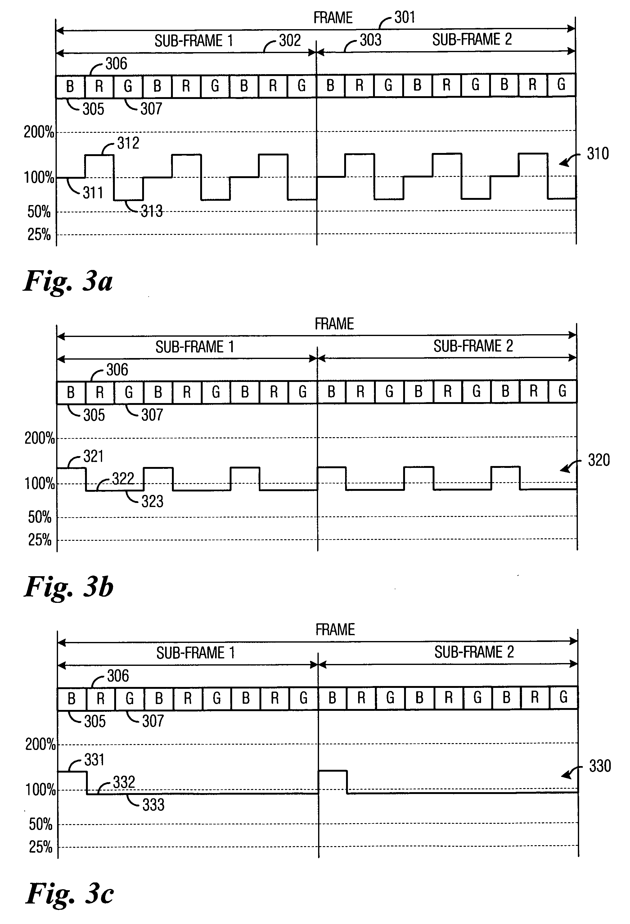
[0014] An advantage of a preferred embodiment of the present invention is that the display system's color point can be readily changed without negatively affecting the overall brightness of the display system. Furthermore, significant changes to the color point of the display system can be made without requiring a different color filter, which would enable real-time changes to the color point without requiring mechanical intervention.
[0015] A further advantage of a preferred embodiment of the present invention is that it allows for the attenuation of one or more colors of light to increase the bit-depth of the display system. Furthermore, the attenuation be made when needed as well as to a degree needed, rather than a fixed degree of attenuation at a fixed time interval for a fixed color as would be dictated by a color filter.
[0016] Yet another advantage of a preferred embodiment of the present invention is that in display systems requiring a color wheel, the individual color filters can be maximized in size with maximum transmissivity. This will maximize the brightness of the display system and improve image quality.

Problems solved by technology

Once implemented in the display system, the chromatic characteristics of the display system cannot normally be drastically changed.
One disadvantage of the prior art is that the use of electrical techniques to adjust the color point of the display system can only make small changes to the color point of the display system.
Furthermore, the use of the electrical techniques will tend to decrease the overall brightness of the display system, which can negatively impact the image quality of the display system.
Another disadvantage of the prior art is that the presence of the neutral density filter on the color wheel (such as the color wheel 125 (FIG. 1b)) can reduce the overall size of the other color filters on the color wheel.
This will reduce the overall ability of the display system to produce the other necessary colors of the display system and thereby negatively affect the image quality of the display system.
For example, the presence of the neutral density filter can reduce the overall brightness of the display system and affect the quality of the images being displayed.
Furthermore, a single neutral density filter will only be able to provide a single fixed attenuation of the light.

Method used


Image

  • System and method for displaying images
  • System and method for displaying images
  • System and method for displaying images

Examples


Embodiment Construction

[0024] The making and using of the presently preferred embodiments are discussed in detail below. It should be appreciated, however, that the present invention provides many applicable inventive concepts that can be embodied in a wide variety of specific contexts. The specific embodiments discussed are merely illustrative of specific ways to make and use the invention, and do not limit the scope of the invention.

[0025] The present invention will be described with respect to preferred embodiments in a specific context, namely a three-color display system making use of a digital micromirror device (DMD). The invention may also be applied, however, to other display systems, such as those that make use of more than three colors or display systems using other technologies of light modulators, such as deformable mirrors, liquid crystal display, liquid crystal on silicon, and so forth. Furthermore, the invention can be applied to display systems using a variety of light sources, such as t...


PUM


Abstract

System and method for enhancing image quality in a display system. A preferred embodiment comprises a variable light source capable of producing a light of specified intensity and color, an array of light modulators optically coupled to the variable light source, the array to modulate the light based upon image data to display images on a display plane, a controller coupled to the array, the controller to issue commands to control the array, and a light driver circuit coupled to the variable light source and the controller, the light driver circuit to provide a signal to the variable light source to specify the intensity of the light produced by the variable light source, when there is a change in a color of light being displayed or when a change in a weight of the image data to be displayed requires less light to be displayed than a current output level.

Description

TECHNICAL FIELD [0001] The present invention relates generally to a system and a method for displaying images, and more particularly to a system and a method for enhancing image quality in a display system. BACKGROUND [0002] Display systems using spatial light modulators use a light source to provide a light that is used to project images onto a display plane. The light source may comprise a single, wide-band light source used in conjunction with color filters to produce light of desired colors. For example, in a three-color display system, color filters may be used to produce light in red, green, and blue wavelengths. In display systems that use other color combinations, different color filters can be used to provide the desired colored light. Alternatively, the light source may comprise multiple, narrow-band light sources that are selected to produce light of desired colors. For example, a three-color display system can include three light sources, with a first light source produc...

Claims


Application Information

Patent Timeline
IPC IPC(8): G09G3/34
CPCG09G3/2025G09G3/3413G09G2310/0235G09G2320/0666G09G2320/0633G09G2320/0646G09G2310/08
Inventor VESTAL, GREGORY SCOTTBELLIS, HAROLD E. II
Owner TEXAS INSTR INC
Learn More