Photosensitive sensor unit for image scanner to improve its spectral accuracy and raise bit depth

A photosensitive sensor, sensor technology, applied in image communication, radiation control devices, picture signal generators, etc., can solve problems such as inability to provide, high input sampling rate, etc.

Inactive Publication Date: 2002-12-11
HEWLETT PACKARD CO
View PDF5 Cites 0 Cited by
  • Summary
  • Abstract
  • Description
  • Claims
  • Application Information

AI Technical Summary

Problems solved by technology

Large sensor area provides high signal-to-noise ratio, high bit depth and high speed, but not high input sampling rate

Method used


Image

  • Photosensitive sensor unit for image scanner to improve its spectral accuracy and raise bit depth
  • Photosensitive sensor unit for image scanner to improve its spectral accuracy and raise bit depth
  • Photosensitive sensor unit for image scanner to improve its spectral accuracy and raise bit depth

Examples


Embodiment Construction

[0022] specific implementation plan

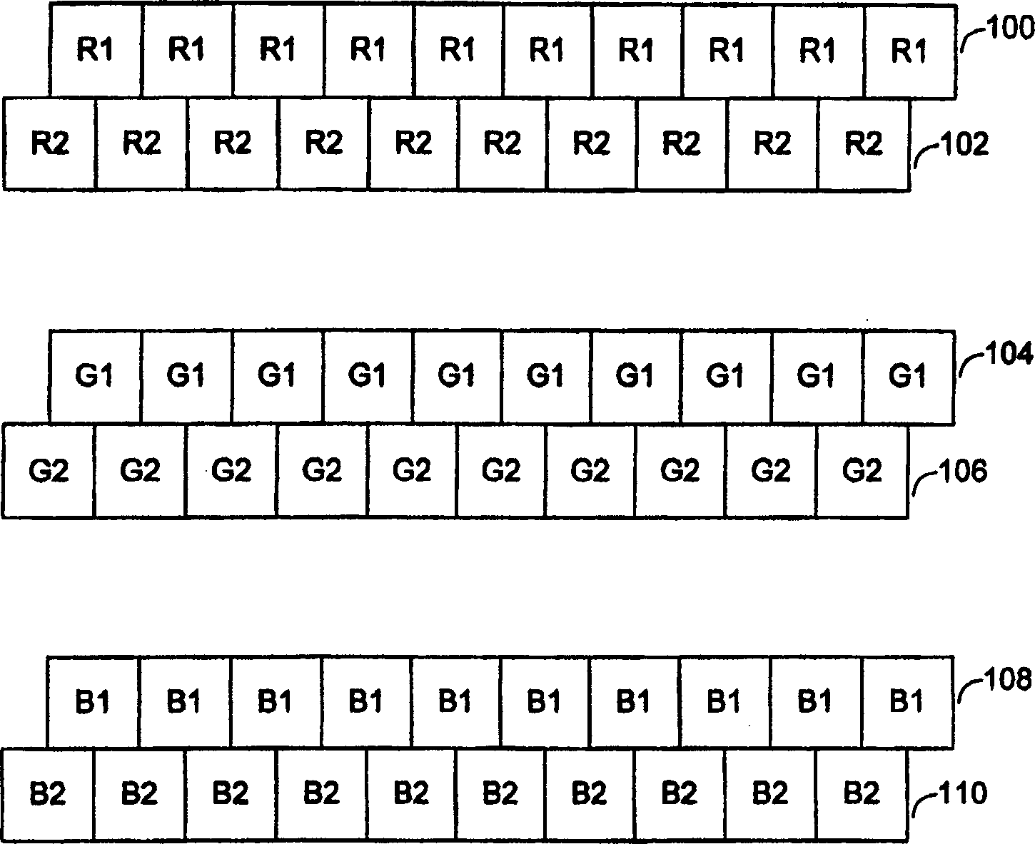
[0023] figure 1 Several groups are shown (in the figure 1 Three pairs in the example) staggered rows of photosensitive sensors. exist figure 1 In the example of , the pitch and width of the photosensors in each row are the same, and each row is offset by half the pitch of the photosensors, or half the width of the photosensors. For demonstration purposes, figure 1 Structural details of non-photosensitive sensors are omitted. A known figure 1 The shown geometric arrangement of staggered rows of photosensitive sensors is used in an image scanner. The photosensitive sensors may overlap as shown, or may not overlap in a grid configuration (see, eg, US Patents 4,432,017 and 4,994,907). Conventionally, all photosensors in a set of staggered rows of photosensors receive light with the same spectral bandwidth as a result of beam splitting or filtering. For example, conventionally, all photosensors in the group of rows 100 and 102 receive l...


PUM


Abstract

A photosensitive sensor device has multiple row arrays for each color. For each color, the spectral bandwidth received by each row array is different. Additional spectral bandwidth is used to improve spectral measurement accuracy and to increase bit depth. In one example, a row of interleaved arrays (100, 104, 108) receives light having a first spectral bandwidth, while a second row of interleaved arrays (102, 106, 110) receives light having a different spectral response. In a second example, photosensitive sensors (200, 202, 204) (206, 208, 210) having different sizes receive light having different spectral bandwidths.

Description

technical field [0001] The present invention relates generally to photosensitive sensor arrays for use in image scanners, copiers and facsimile machines, and more particularly to photosensitive sensor devices with improved spectral accuracy. Background technique [0002] Image scanners, also known as document scanners, convert visual images of documents or photographs, or images on transparent media, into electronic form suitable for reproduction, storage or processing by a computer. The image scanner can be a stand-alone device, or the image scanner can be part of a copier, part of a facsimile machine, part of a multipurpose device. Reflective image scanners typically have a controlled light source, and the light is reflected from the surface of the document through an optical system to an array of photosensitive devices. Transparent image scanners pass light through a transparent image, such as a slide positive of a photograph, through an optical system, and then to an ar...

Claims


Application Information

Patent Timeline
Patent Type & Authority Applications(China)
IPC IPC(8): H01L27/148H04N1/028H04N1/48H04N5/361H04N5/372H04N9/04
CPCH04N1/486H04N25/701
Inventor R·G·甘K·E·斯佩尔斯
Owner HEWLETT PACKARD CO
Why Eureka
Try Eureka