
Vacuum assisted treatment of the skin

a technology of skin and assisted treatment, applied in the field of skin care, can solve the problems of inability to achieve the effect of facilitating and rapid movemen

Inactive Publication Date: 2009-04-02
CANDELA CORP
View PDF90 Cites 67 Cited by
  • Summary
  • Abstract
  • Description
  • Claims
  • Application Information

AI Technical Summary

Benefits of technology

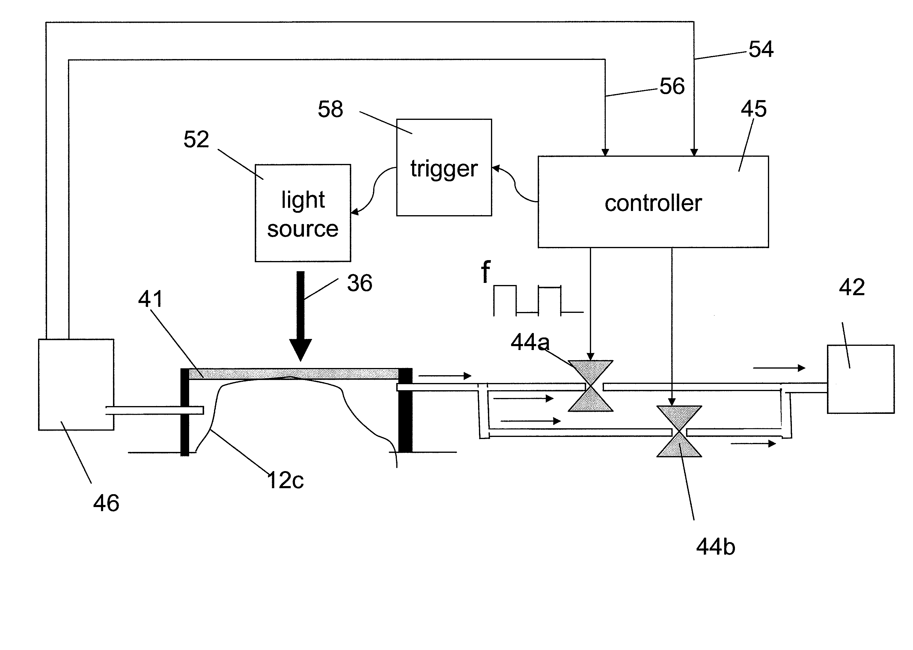
[0004]The invention features, in one embodiment, a vacuum assisted treatment device including a chamber that can be used to partially evacuate air over a target region of skin. The device need not push upon or against flexible skin when placed on or near the skin. Instead, the device senses when the chamber is adjacent or proximate the skin, and can begin to generate vacuum. Furthermore, the device can include a mechanism to deactivate the vacuum so that the device can be easily and rapidly moved between target regions.
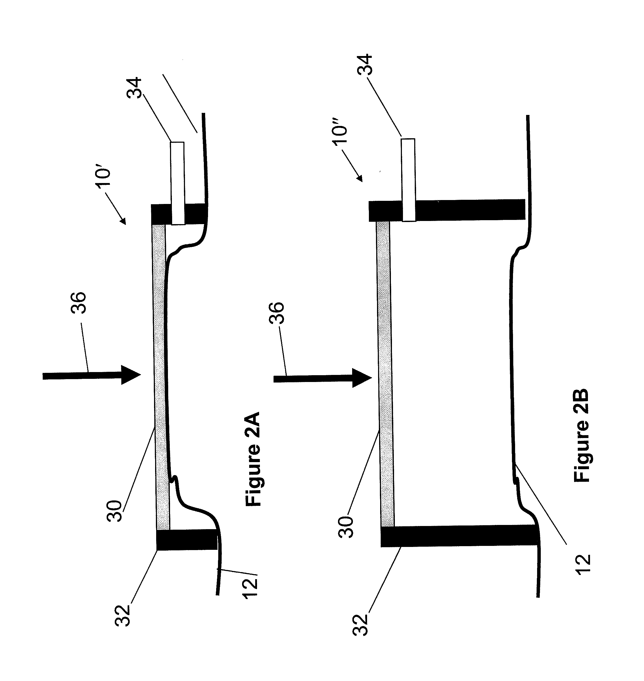
[0012]The chamber can be capable of forming the substantially fluid tight seal between the rim of the chamber and soft skin. The substantially fluid tight seal can be released by decreasing the rate of removal of the air from inside the chamber after a predetermined time interval following achieving the threshold value. The rate of removal of air can be decreased using a mechanism that introduces air into the chamber. In some embodiments, the substantially fluid tight seal can be released by introducing air into the chamber after a predetermined time interval following achieving the threshold value. The apparatus can include a distance gauge to facilitate placement of the chamber at, adjacent, near, or proximate to the skin. In certain embodiments, an index matching layer can be disposed on an outer surface of the chamber to facilitate delivery of the electromagnetic radiation.

Problems solved by technology

Although generally satisfactory, a disadvantage of the utilization of a micro-switch on the skin can result if the skin lacks stiffness or rigidity.
Consequently, a treatment may be more difficult, or in certain circumstances, may not be feasible.

Method used


Image

  • Vacuum assisted treatment of the skin
  • Vacuum assisted treatment of the skin
  • Vacuum assisted treatment of the skin

Examples


Embodiment Construction

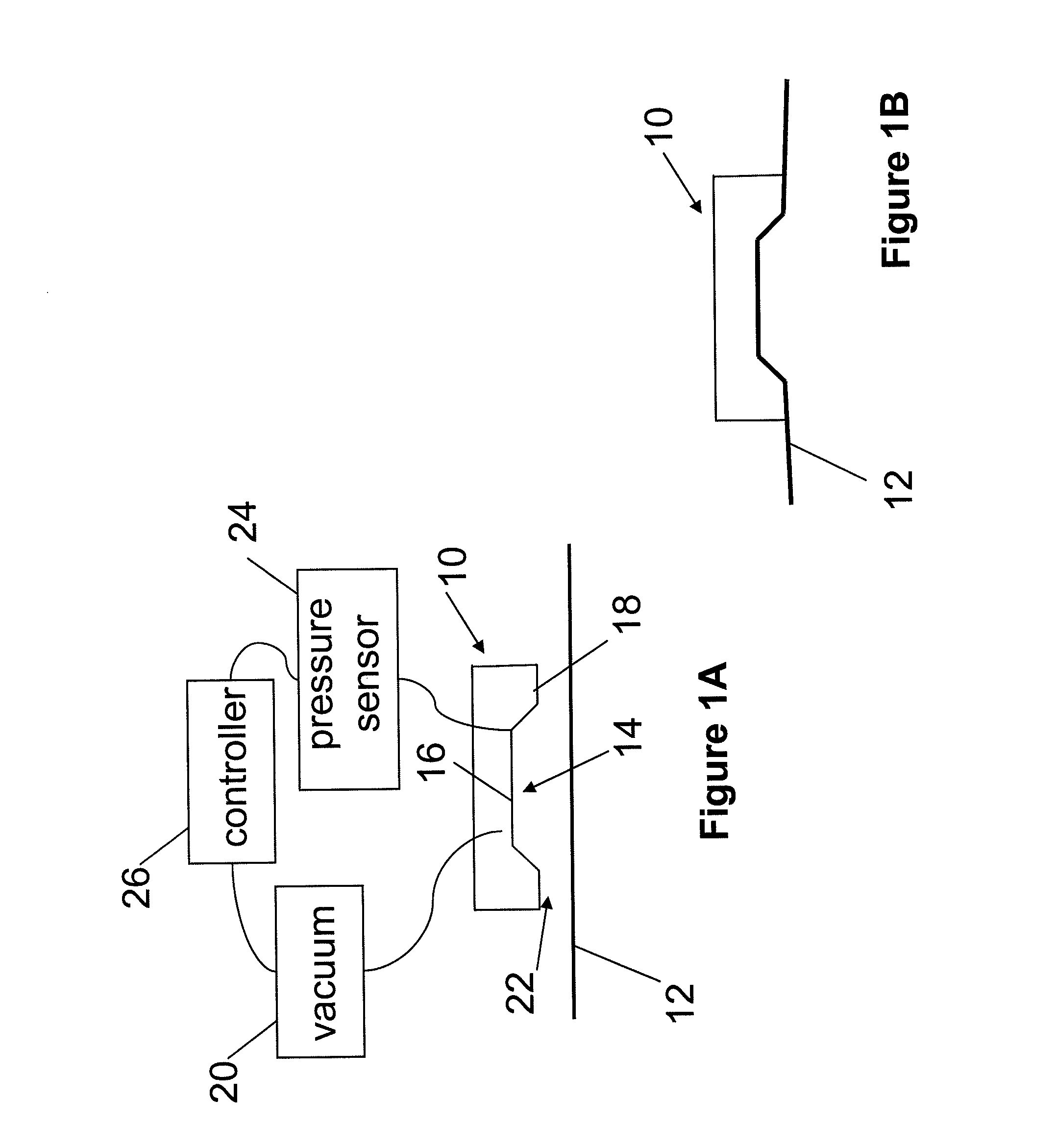
[0024]FIG. 1A shows an apparatus 10 for treating skin 12. The apparatus 10 includes a chamber 14 defined by a surface 16 and a rim 18 extending from the surface. A source 20 of vacuum is in fluid communication with the chamber 14. The source 20 of vacuum is capable of removing air from inside the chamber 14 so that air outside the chamber 14 flows into the chamber 14. Impedance of the air flowing between 22 the rim 18 of the chamber positioned adjacent the skin 12 surface causes the pressure inside the chamber 14 to decrease relative to ambient. A pressure sensor 24 is in fluid communication with the chamber. The pressure sensor 24 determines when the pressure inside the chamber 14 decreases to a threshold value. A controller 26 is in electrical communication with the source 20 of vacuum and the pressure sensor 24. The controller 26 receives a signal from the pressure sensor 24 when the threshold value is reached, which causes the rate of removal of the air from inside the chamber 1...


PUM


Abstract

An apparatus for treating skin includes a chamber defined by a surface and a rim extending from the surface. A source of vacuum is capable of removing air from inside the chamber so that air outside the chamber flows into the chamber. Impedance of the air flowing between the rim of the chamber positioned adjacent the skin surface causes the pressure inside the chamber to decrease relative to ambient. A pressure sensor can determine when the pressure inside the chamber decreases to a threshold value. A controller can receive a signal from the pressure sensor when the threshold value is reached, which causes the rate of removal of the air from inside the chamber by the source of vacuum to be increased. The rim of the chamber forms a substantially fluid tight seal with the skin. The skin is drawn toward an inner surface of the chamber.

Description

FIELD OF THE INVENTION[0001]The invention is related to vacuum assisted treatments of the skin, and more particularly to creating a partial vacuum over the skin using a chamber positioned adjacent a surface of the skin in a target region.BACKGROUND OF THE INVENTION[0002]Vacuum assisted treatment of the skin has recently been described in several patent applications, including: U.S. patent application Ser. No. 11 / 498,456; U.S. patent application Ser. No. 11 / 401,674; EP Patent Application No. 050007952.4; U.S. patent application Ser. No. 11 / 057,542; U.S. patent application Ser. No. 10 / 498,382; and PCT / IL02 / 00635, the disclosures of which are herein incorporated by reference in their entirety. Clinical applications of vacuum assisted treatments of the skin include, among others, light based aesthetic treatments of the skin such as hair removal, treatment of pigmented lesions, and treatment of vascular lesions as well as medical treatments such as painless injections. An evacuation cham...

Claims


Application Information

Patent Timeline
Patent Type & Authority Applications(United States)
IPC IPC(8): A61N5/067A61M1/00A61N1/30
CPCA61B18/203A61B2017/00752A61B2017/00761A61B2017/00769A61B2017/308A61N2005/0644A61B2018/00476A61B2018/1807A61B2019/464A61M1/0031A61M1/0088A61B2018/00452A61B2090/064A61M2210/04A61M2205/13A61M1/74A61M1/96
Inventor BARAK, MENASHEMISHALI, SHLOMISHAVIT, RAPHISLATKINE, MICHAEL
Owner CANDELA CORP
Learn More