
Cleaning device, cleaning tool and method of using the cleaning device

a cleaning device and cleaning tool technology, applied in the direction of steam generation using steam absorption, steam boiler components, hollow article cleaning, etc., can solve the problems of heavy work and risk, and achieve the effect of minimal manual effort and efficient cleaning

Inactive Publication Date: 2009-04-09
EIE MASKIN
View PDF3 Cites 0 Cited by
  • Summary
  • Abstract
  • Description
  • Claims
  • Application Information

AI Technical Summary

Benefits of technology

[0003]A first object of the present invention is to provide a cleaning device that is efficient in cleaning. A second object of the present invention is to provide a cleaning device that is useful for automatic cleaning. A third object of the present invention is to provide a cleaning tool for use in the cleaning device. A fourth object of the present invention is to provide methods to use the cleaning device that give the intended cleaning effect and simultaneously require minimal manual effort.
[0012]Said front tool part may in turn comprise at least one first cleaning part and at least one first holder part with bracket, said first cleaning part having a shape and size that closely connects to the corresponding shape and size of an outlet port or the like that is to be cleaned, so that said first cleaning part, if required, can be inserted into the outlet port and clean the same from solidified soda, cinder or the like. Said rear tool part may in turn comprise at least one second cleaning part and at least one second holder part with bracket, said second cleaning part having a shape and size that closely connects to the corresponding shape and size of the interior of an outlet spout or the like that is to be cleaned, so that said second cleaning part, if required, can be inserted into the outlet spout and clean the same from solidified soda, cinder or the like.

Problems solved by technology

This work is heavy and risky.

Method used


Image

  • Cleaning device, cleaning tool and method of using the cleaning device
  • Cleaning device, cleaning tool and method of using the cleaning device
  • Cleaning device, cleaning tool and method of using the cleaning device

Examples


Embodiment Construction

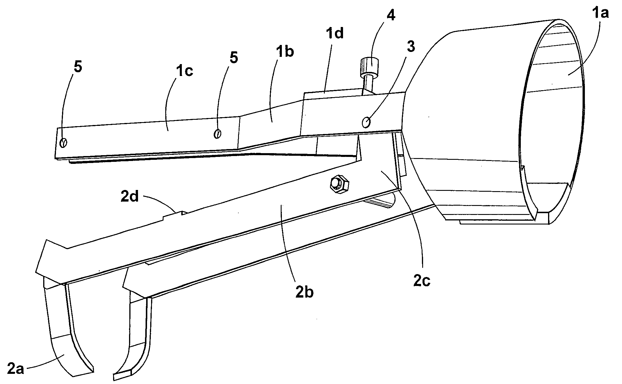
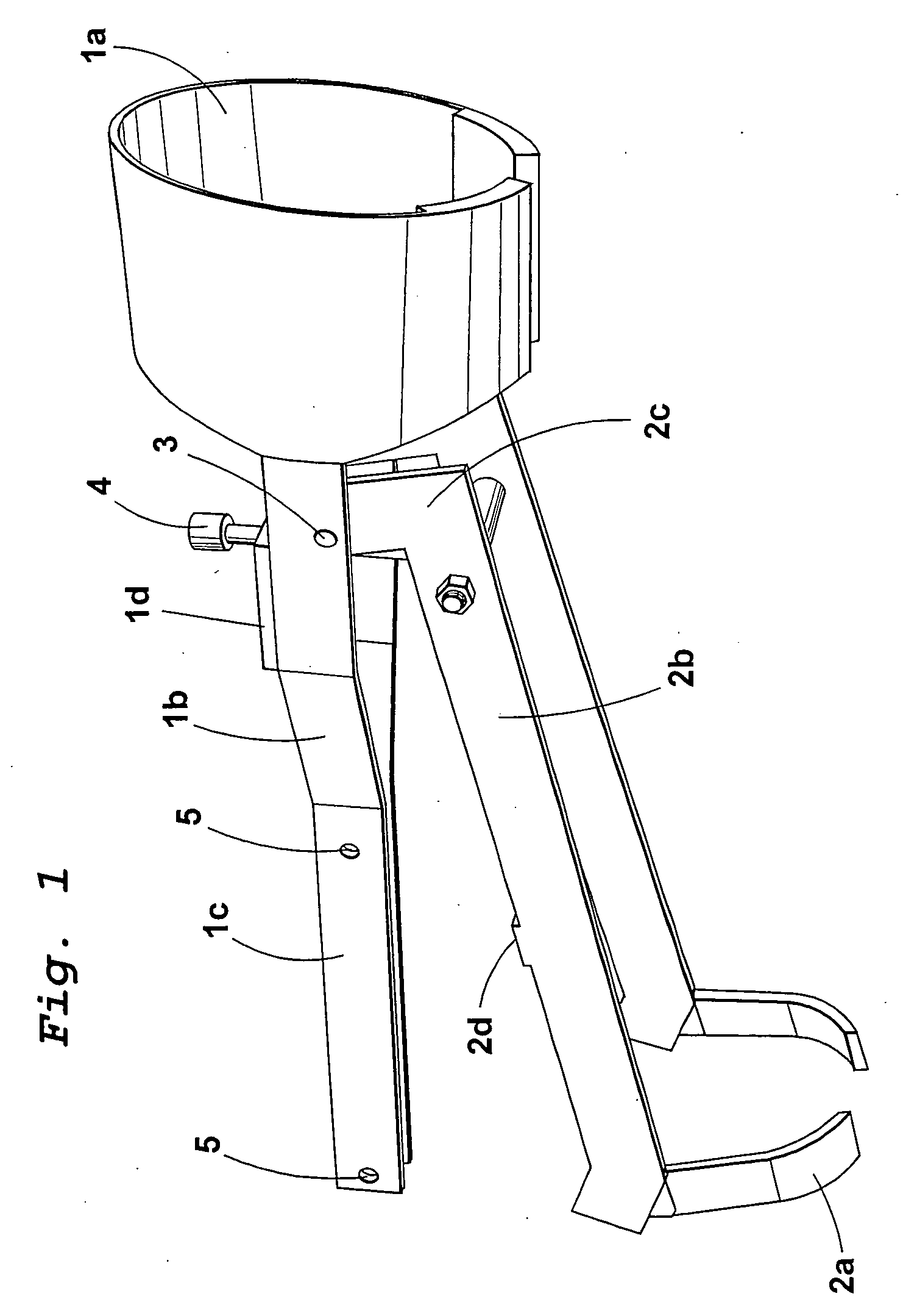
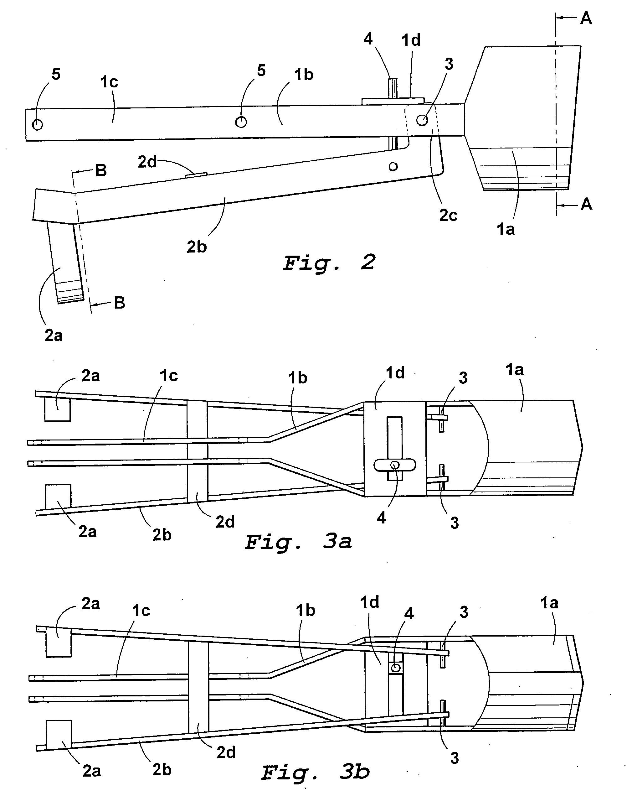
[0031]From FIGS. 1-3 is evident how two parts of a cleaning tool according to the invention included in a cleaning device according to the invention appear and are assembled, viz. a front tool part 1a-d, 3, 6 and a rear tool part 2a-d. The front tool part 1a-d, 3, 6 comprises a first cleaning part 1a, a first holder part 1b with bracket 1c and a first strut 1d. The rear tool part 2 comprises a second cleaning part 2a, a second holder part 2b with bracket 2c and a second strut 2d. The front tool part 1a-d, 3, 6 and the rear tool part 2a-d are articulatedly interconnected with each other around the axle journals 3 that are fixedly connected to the first cleaning part 1a via the first holder part 1b. An adjustment device 4 enables adjustment of the desired angle between the first and second holder parts 1b and 2b. In the first holder part 1b, there are, in the bracket 1c, holes 5 for bolts or the like for mounting the first holder part 1b on a connecting rod or the like.

[0032]From FIG....


PUM

PropertyMeasurementUnit
lengthaaaaaaaaaa
areaaaaaaaaaaa
temperatureaaaaaaaaaa

Abstract

The present invention relates to a cleaning device for cleaning outlet ports (11) or the like and / or outlet spouts (12) or the like in soda recovery boilers (13) or the like, the cleaning device comprising at least one connecting rod (9). The cleaning device has at least one front tool part (1a-d, 3, 6), mounted on said connecting rod (9).The present invention also relates to a cleaning tool for use in the cleaning device as well as a method of using the cleaning device.

Description

[0001]The present invention relates to a cleaning device for cleaning outlet ports or the like and / or outlet spouts or the like in soda recovery boilers or the like. The invention also relates to a cleaning tool for use in the cleaning device as well as two methods of using the cleaning device.PRIOR ART[0002]Liquid soda that is tapped from a soda recovery boiler usually passes at least one outlet port and an outlet spout located under the same. The soda running out of the boiler has a temperature of approx. 1000° C. and, upon contact with air, a part of the soda solidifies and forms a solid “covering” in the port and the spout. Solidified soda blocks the flow and it occurs that lumps are to pass in the spout as well as that liquid soda splashes out in the boiler room. The usual way today to prevent that solidified soda blocks the flow is to clean outlet ports and outlet spouts manually at regular intervals by means of long levers. This work is heavy and risky.SUMMARY OF THE INVENTIO...

Claims


Application Information

Patent Timeline
Patent Type & Authority Applications(United States)
IPC IPC(8): B08B9/00B01BB08B9/027B08B13/00D21CD21C11/10D21C11/12F22B1/20F22B37/48
CPCD21C11/106B08B1/00D21C11/12
Inventor ERIKSSON, ULFJANSSON, PAR-AKE
Owner EIE MASKIN
Learn More