Anti-slip footwear

a technology of anti-slip shoes and waterproofing, applied in the field of footwear, can solve the problems of personal injuries or even unexpected deaths, wearers are very likely to fall on the ground, and shoes for pools and streams have their own limitations, and achieve the effect of increasing traction

Inactive Publication Date: 2009-04-09
JUNG MAN YOUNG
View PDF12 Cites 86 Cited by
  • Summary
  • Abstract
  • Description
  • Claims
  • Application Information

AI Technical Summary

Benefits of technology

[0012]In another embodiment of the present invention, a moisture repellant tread for attachment to an outsole of a shoe comprises a base plate having a top surface locally bonded to the outsole with a lateral clearance between the base plate and outsole about the bonded areas, a bottom surface for contacting a floor and multiple closely arranged recesses open to the bottom surface and communicating throug

Problems solved by technology

There are many reports of personal injuries or even unexpected deaths from falls on surrounding hard surfaces stemming from normal shoes or slippers unfortunately stepped on an unsuspected wetted spot.
However, when the shoes wear out and then caught in a slippery situation, the wearer does very likely

Method used


Image

  • Anti-slip footwear
  • Anti-slip footwear
  • Anti-slip footwear

Examples


first embodiment

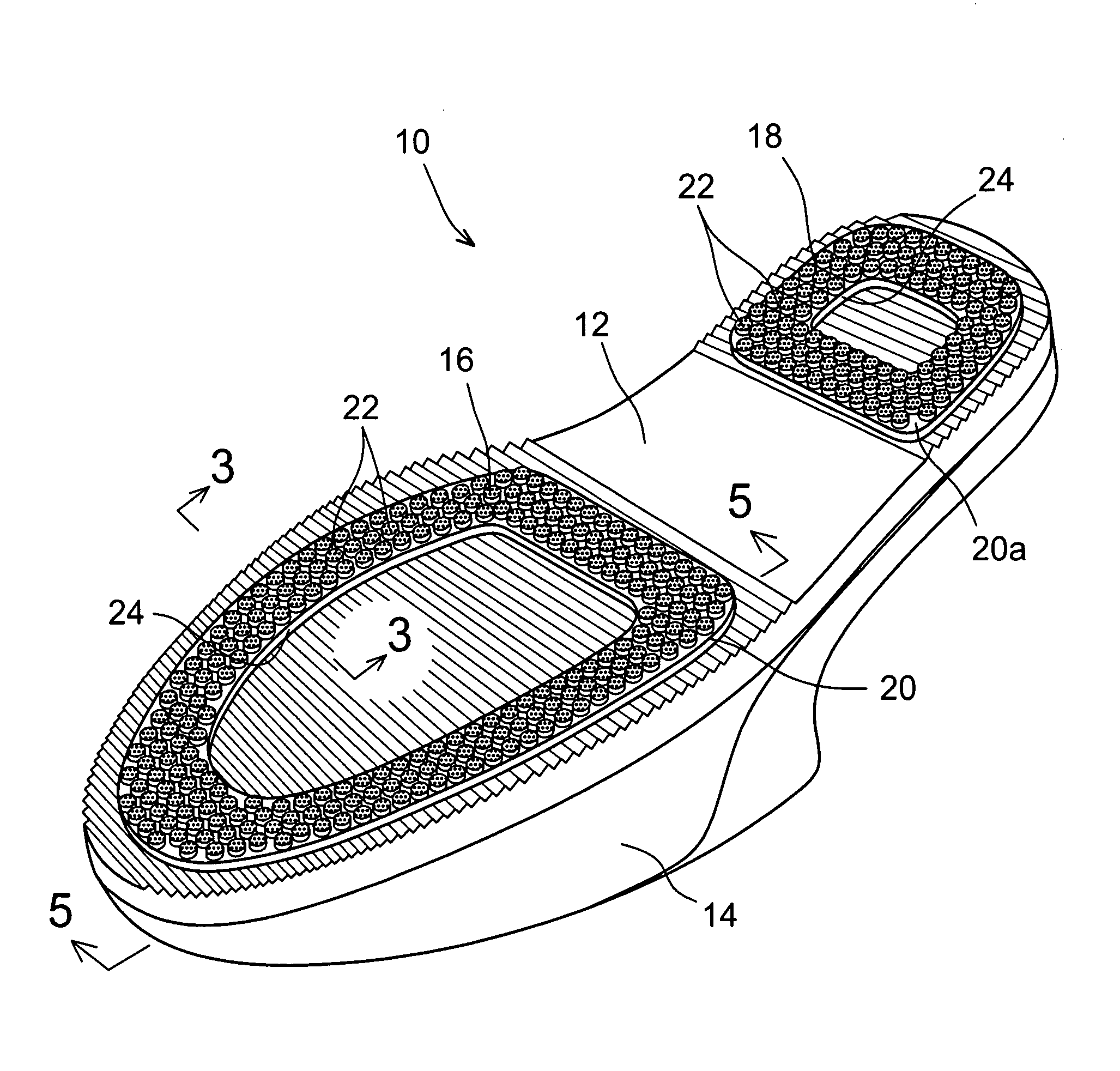
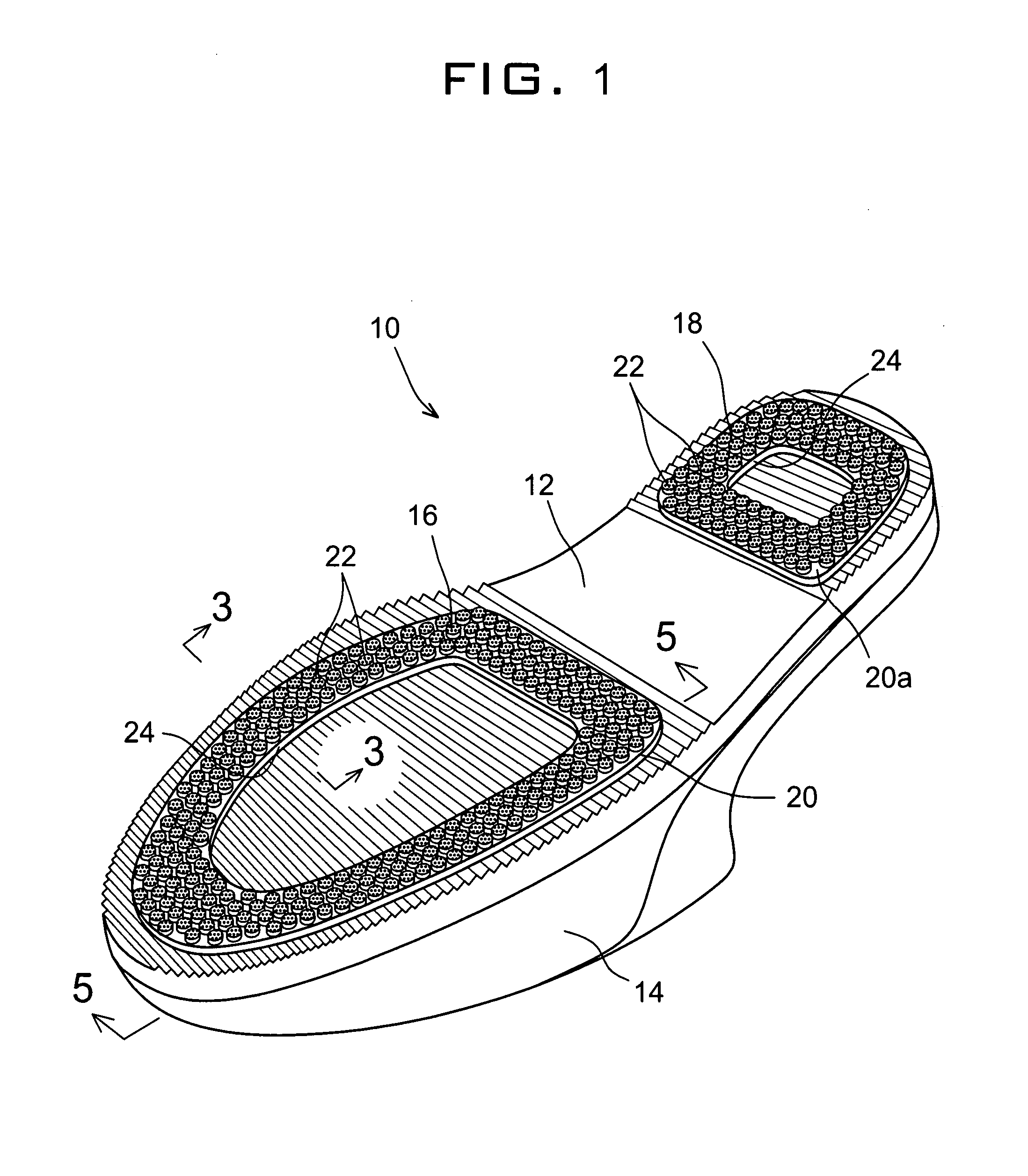
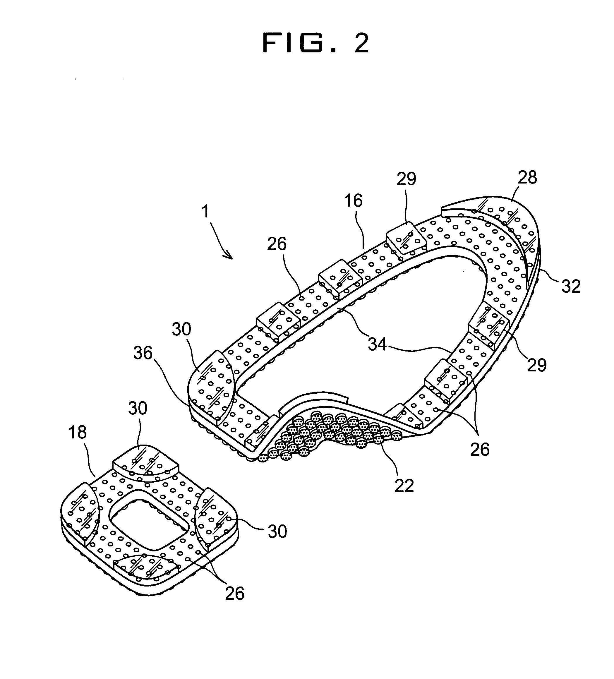
[0025]FIG. 2 specifically shows a sole tread 1 of the present invention in a perspective view from the top. Sole tread 1 is adapted to be attached by a wearer to the underside of an existing shoe, which has a shaped tread 26 as exemplified in FIG. 1 but is insufficient to prevent the wearer from slipping at the presence of floor water. Tread 1 in the drawing is partially flexed to show fiber bundles 22 on the underside for contacting the floor safely after it is fixed to the shoe 10. Sole tread 1 provides just enough traction on a surface whether it is dry or wet without compromising the natural walking postures of the wearer or aesthetical value of the general conventional portion of the shoe 10 due to its thin and light structure only using the similar materials used for sole 12 and very light strands of fibers 22. Tread attachment 1 has larger sole section 16 and smaller heel section 18 that can be formed either integrally or separately and are provided with multiple thru holes 2...

second embodiment

[0032]Referring to FIGS. 4 and 5 showing the bottom of side area 34 in section cut lengthwise with respective to widthwise as in FIG. 3, the sole tread 100 of the present invention is good for both custom attachment to existing shoes and integration into the shoe manufacturing at the sole making and bonding processes. Tread 100 has a base plate 101 with an additional solid top surface 102 that can provide a bonding surface in its entirety in order to provide a better bonding of tread 100 by an end user or in the manufacturing process where the sole 12 may be formed integral to the inventive tread 100.

[0033]In order to provide channels for displacing water, tread 100 further includes lateral apertures 104 for communicating holes 26 to side open spaces between sole 12 (FIG. 1) and tread 100. Upon attachment of tread 100 to the shoe 10 slightly protruding fiber bundles 22 collectively work to provide a unique advantage of positive displacement of water to sideways through apertures 104...


PUM


Abstract

A moisture repellant tread is provided for a positive displacement of moisture to secure the traction in the bottom of a shoe. The tread comprises a base plate and multiple short bundles of absorbent fibers. The base plate has a top surface locally bonded to the outsole with a lateral clearance between the base plate and outsole about the bonded areas, a bottom surface for contacting a floor and multiple closely arranged recesses open to the bottom surface and communicating through smaller openings formed at the top surfaces concentrically of the recesses. The fiber bundles are partially implanted in the recesses for displacing water absorbed from the floor upon contact through the openings at the top surfaces to the lateral clearance whereby the tread secures an increased traction as a wearer steps on the tread through the shoe even on a film of moisture.

Description

BACKGROUND OF THE INVENTION[0001]A. Field of the Invention[0002]The present invention relates to footwear. More particularly, the present invention relates to moisture repelling shoes for preventing an injurious slippage and a tread attachment with moisture repellant effect for transforming common footwear into a slip-resistant foot protection.[0003]B. Description of the Prior Art[0004]The negative phenomenon of hydroplaning originally describes the unfortunate incidents in driving in rain or through a wet road where the footing of a vehicle, i.e. tires fail to grip the ground losing the decisive traction for keeping the safe travel of the vehicle and its occupants. The similar incidents are experienced by common walking individuals in the daily lives at the comfort of homes as well as busy work locations. There are many reports of personal injuries or even unexpected deaths from falls on surrounding hard surfaces stemming from normal shoes or slippers unfortunately stepped on an un...

Claims


Application Information

Patent Timeline
IPC IPC(8): A43C15/00
CPCA43B13/14A43B13/223A43B13/22
Inventor JUNG, MAN-YOUNG
Owner JUNG MAN YOUNG
Why Eureka
Try Eureka