Steering hanger beam

a technology of steering hanger and beam, which is applied in the direction of steering columns, transportation and packaging, understructures, etc., can solve the problems of deteriorating a degree of freedom of design of vehicle bodies, complex structure, and simplified reinforcing parts, so as to ensure the strength and rigidity of the steering hanger beam, and improve the ground performance of the vehicle body

a technology of steering hanger and beam, which is applied in the direction of steering columns, transportation and packaging, understructures, etc., can solve the problems of deteriorating a degree of freedom of design of vehicle bodies, complex structure, and simplified reinforcing parts, so as to ensure the strength and rigidity of the steering hanger beam, and improve the ground performance of the vehicle body

US20090090211A1Inactive Publication Date: 2009-04-09HONDA MOTOR CO LTD

Image

  • Steering hanger beam
  • Steering hanger beam
  • Steering hanger beam

Examples


Embodiment Construction

[0058]Hereinunder, an exemplary embodiment of the invention will be described with reference to the accompanying drawings.

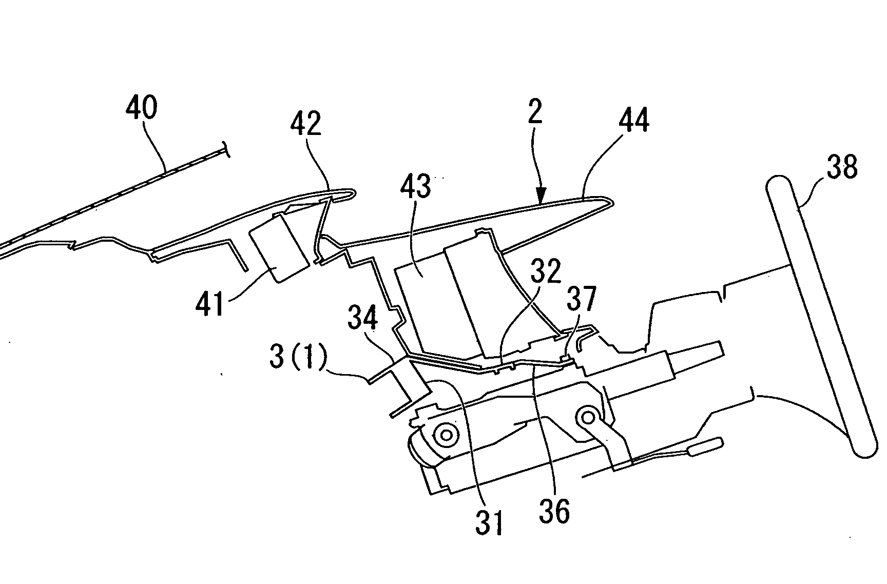
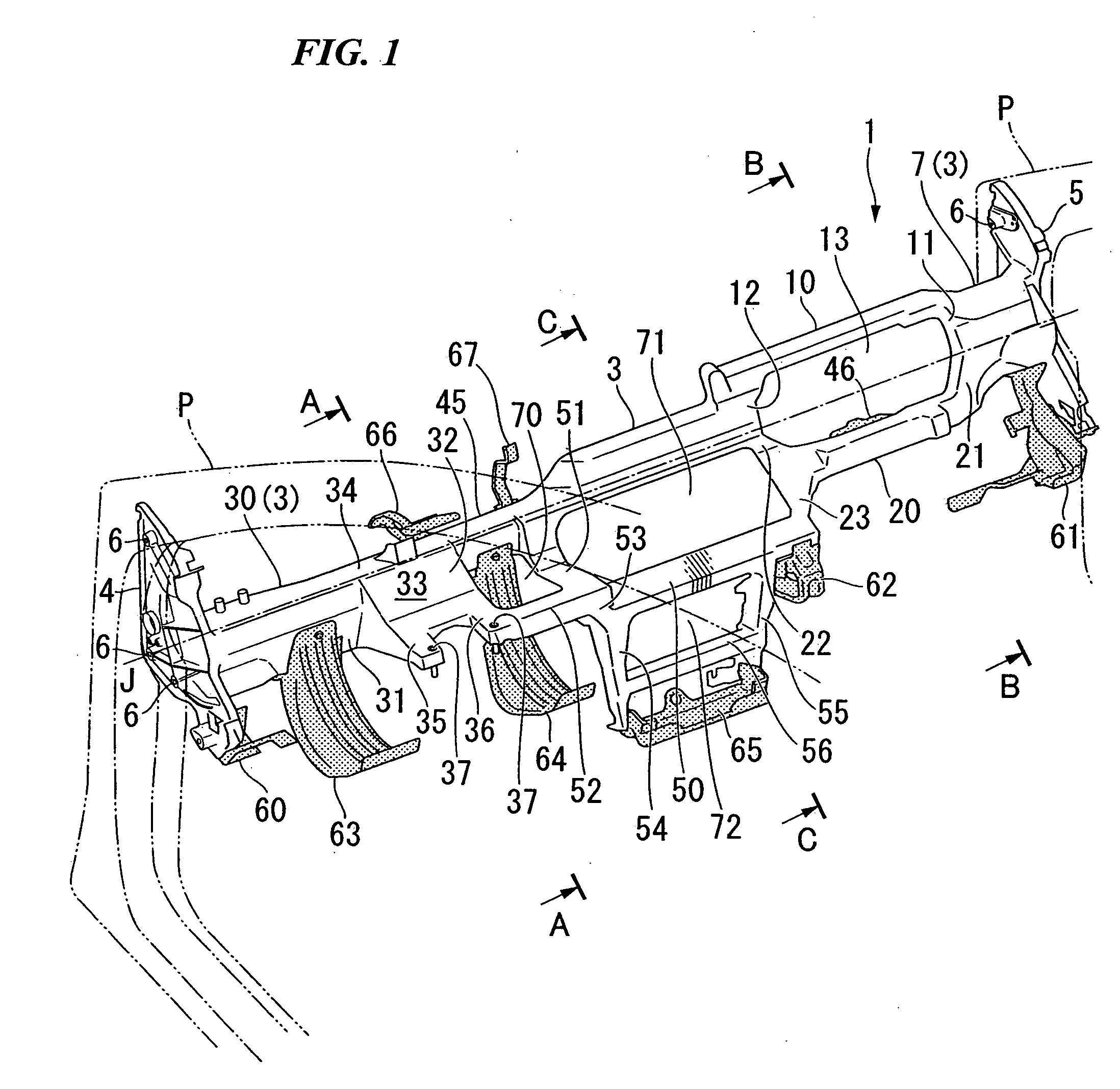
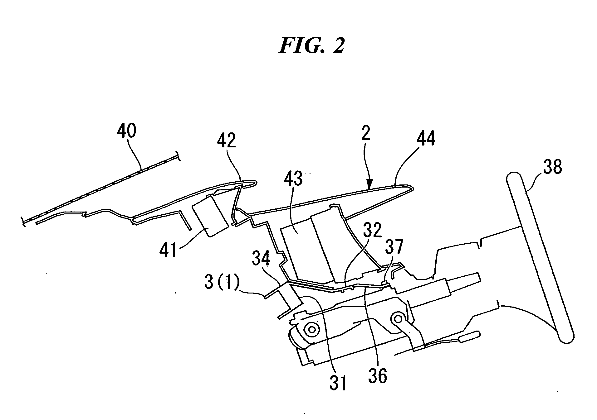
[0059]FIG. 1 shows a steering hanger beam 1 according to the embodiment of the present invention, and the steering hanger beam 1 is used for a so-called left handle type in which a driver seat is disposed on the left side and a passenger seat is disposed on the right side as shown in FIG. 1. The steering hanger beam 1 is mainly formed of a magnesium alloy by die-casting and is covered by an instrument panel 2 described below.

[0060]The steering hanger beam 1 includes a main member 3 extending in a width direction of a vehicle so as to substantially extend in a horizontal direction. A left mounting portion 4 mounted to an inner wall of a left front pillar P is provided in an end portion of the main member 3 on the driver-seat side so as to be aligned in a width direction of a vehicle. A right mounting portion 5 mounted to an inner wall of a right front pillar P is ...


PUM


Abstract

The steering hanger beam extending in a width direction of a vehicle and connected to left and right vehicle-body members, is provided with: a main member which supports a steering device; a pair of front and rear transverse beam portions connected to the main member in the width direction of the vehicle so as to be offset from an axis of the main member to front and rear; and an opening which is formed between the pair of front and rear transverse beam portions so as to penetrate in substantially a vertical direction.

Description

BACKGROUND OF THE INVENTION[0001]Priority is claimed on Japanese Patent Application No. 2007-261171, filed on Oct. 4, 2007, Japanese Patent Application No. 2007-262354, filed on Oct. 5, 2007, and Japanese Patent Application No. 2007-264463, filed on Oct. 10, 2007, the contents of which are incorporated herein by reference.[0002]1. Field of the Invention[0003]The present invention relates to a steering hanger beam.[0004]2. Description of the Related Art[0005]Conventionally, a vehicle-body structure having a light-alloy steering support member is known. In such a structure, an airbag is mounted to the upper portion of the steering support member (for example, see Japanese Unexamined Patent Publication, First Publication No. 2005-289239).[0006]In the above-described related art, since the airbag is mounted to the upper portion of the steering support member on the basis of the steering support member, the height of an upper surface of an instrument panel increases. For this reason, for...

Claims


Application Information

Patent Timeline
09 Apr 2009
Publication
US20090090211A1
IPC
B62D1/16
CPC
B62D25/145
Inventors
KUWANO, YOHEI