Method for Dynamically Compensating for a Faulty Pixel in a Scan Line Generated by a Scanner

a dynamic compensation and scan line technology, applied in the field of scanning methods, can solve the problems of affecting cost, lowering the overall yield of the product, weak or dead sensor elements in the scanner cannot be compensated by traditional methods, etc., and achieve the effect of reducing or eliminating visible artifacts

Active Publication Date: 2009-04-09
LEXMARK INT INC
View PDF3 Cites 5 Cited by
  • Summary
  • Abstract
  • Description
  • Claims
  • Application Information

AI Technical Summary

Benefits of technology

[0012]The present invention provides a method that automatically detects a faulty pixel and compensates for the faulty pixel to reduce or eliminate visible artifacts that otherwise would be present in the output image.

Problems solved by technology

Certain aspects of the scanner, such as non-uniform illumination and variable response of each individual sensor element (i.e., pixel), make it necessary to correct each individual pixel's light and dark response.
However, a very weak or dead sensor element in the scanner cannot be compensated for by traditional methods.
If such a defect is present on the manufacturing line, the scanner is scrapped, thus lowering the overall yield of the product and affecting cost.
If such a defect occurs during the useful life of the scanner, the quality of the scanned output is greatly degraded.
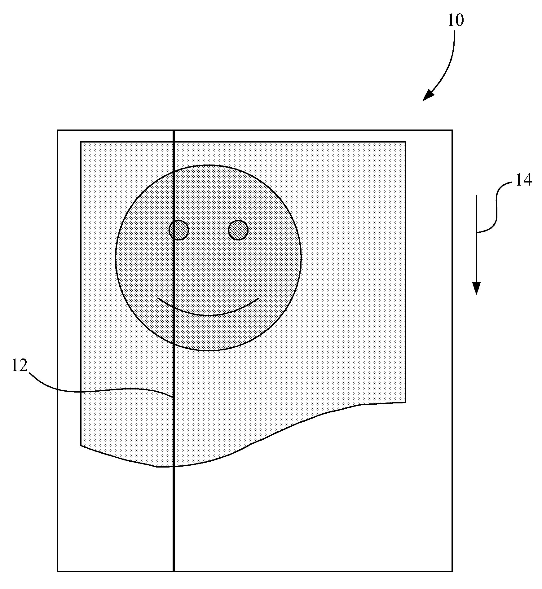
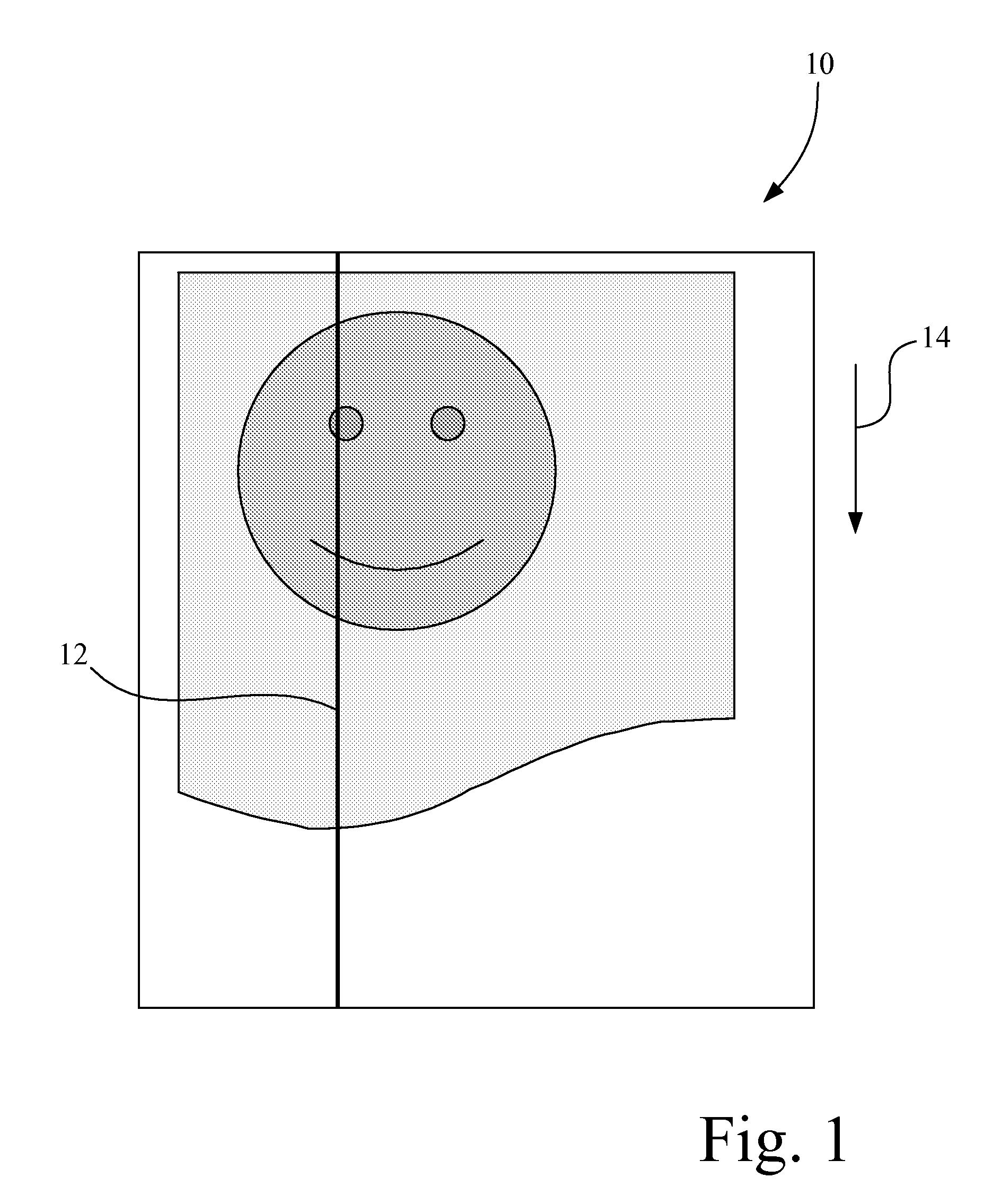
A corrupt pixel, e.g., a very weak or dead sensor element, in the scanner may decrease the performance of an imaging system that utilizes compression on the pixel-to-pixel calibration data, since the white / black response for the pixel is very different than that of the local neighbors of the pixel.
Outlier sensor elements may drastically reduce the capabilities to compress the stored calibration data, which has a detrimental effect on the performance / throughput of a device that is bandwidth starved.

Method used


Image

  • Method for Dynamically Compensating for a Faulty Pixel in a Scan Line Generated by a Scanner
  • Method for Dynamically Compensating for a Faulty Pixel in a Scan Line Generated by a Scanner
  • Method for Dynamically Compensating for a Faulty Pixel in a Scan Line Generated by a Scanner

Examples


Embodiment Construction

[0023]It is to be understood that the invention is not limited in its application to the details of construction and the arrangement of components set forth in the following description or illustrated in the drawings. The invention is capable of other embodiments and of being practiced or of being carried out in various ways. Also, it is to be understood that the phraseology and terminology used herein is for the purpose of description and should not be regarded as limiting. The use of “including,”“comprising,” or “having” and variations thereof herein is meant to encompass the items listed thereafter and equivalents thereof as well as additional items. Unless limited otherwise, the terms “connected,”“coupled,” and “mounted,” and variations thereof herein are used broadly and encompass direct and indirect connections, couplings, and mountings. In addition, the terms “connected” and “coupled” and variations thereof are not restricted to physical or mechanical connections or couplings...


PUM


Abstract

A method for dynamically compensating for a faulty pixel in a scan line of a scanner having an image sensor with a plurality of sensor pixels includes generating digitized scan data; processing the digitized scan data to compensate for any faulty pixels of the plurality of sensor pixels to form compensated scan data; processing the compensated scan data to apply offset and gain correction to the compensated scan data to form calibrated scan data; processing the calibrated scan data to adjust the calibrated scan data to compensate for human visual perception to form final scan data; and storing the final scan data in a scanner image memory.

Description

CROSS REFERENCES TO RELATED APPLICATIONS[0001]None.STATEMENT REGARDING FEDERALLY SPONSORED RESEARCH OR DEVELOPMENT[0002]None.REFERENCE TO SEQUENTIAL LISTING, ETC.[0003]None.BACKGROUND[0004]1. Field of the Invention[0005]The present invention relates generally to scanners and scanning methods, and more particularly to a method for dynamically compensating for a faulty pixel in a scan line of a scanner.[0006]2. Description of the Related Art[0007]An imaging system may include a scanner that is used to generate a digital representation of a document being scanned. Such a document may include any of a variety of media types, such as paper, card stock, etc., and may be regular (e.g., rectangular) or irregular in shape, and on which there is formed, for example, text, graphics or a picture, e.g., a photo, or a combination thereof. Typically, a color scanner generates three channels of data, e.g., red, green and blue (RGB), in generating a scanned image of the document.[0008]When scanning ...

Claims


Application Information

Patent Timeline
Patent Type & Authority Applications(United States)
IPC IPC(8): H04N1/46
CPCH04N1/409H04N1/401
Inventor BAILEY, JAMES RAYCRUTCHFIELD, DAVID ALLEN
Owner LEXMARK INT INC
Why Eureka
Try Eureka